Maintenance routines
Checking the safety valves
FIGHTER 640P has two safety valves, one for the heating
system and one for the water heater.
The heating system’s safety valve (52) must be completely
tight, but the hot water safety valve (47) may occasionally
release some water after hot water has been used. This is
because the cold water, which enters the water heater to
replace the hot water, expands when heated causing the
pressure to rise and the safety valve to open.
The safety valves must be checked regularly. Check one
valve at a time as follows:
Open the valve.•
Check that water flows through the valve.•
Close the valve.•
The heating system may need to be refilled af-•
ter checking the safety valve (52), see the section
“Commissioning and adjusting” – “Filling the heating
system”.
Cleaning the ventilation devices
The building’s ventilation devices should be cleaned regu-
larly with a small brush to keep the correct ventilation.
The device settings must not be changed.
Note! If you take down more than one ventilation device
for cleaning, do not mix them up.
Check that the ventilation opening (84), behind the lower
front cover, is not blocked. Clean if necessary.
Extract air temperature
Check that the temperature of the extract air (channel 5) is
clearly lower than the room temperature when the com-
pressor is operational, also see the section “Dealing with
malfunctions” – “High extract air temperature”. It is nor-
mal that the extract air temperature varies.
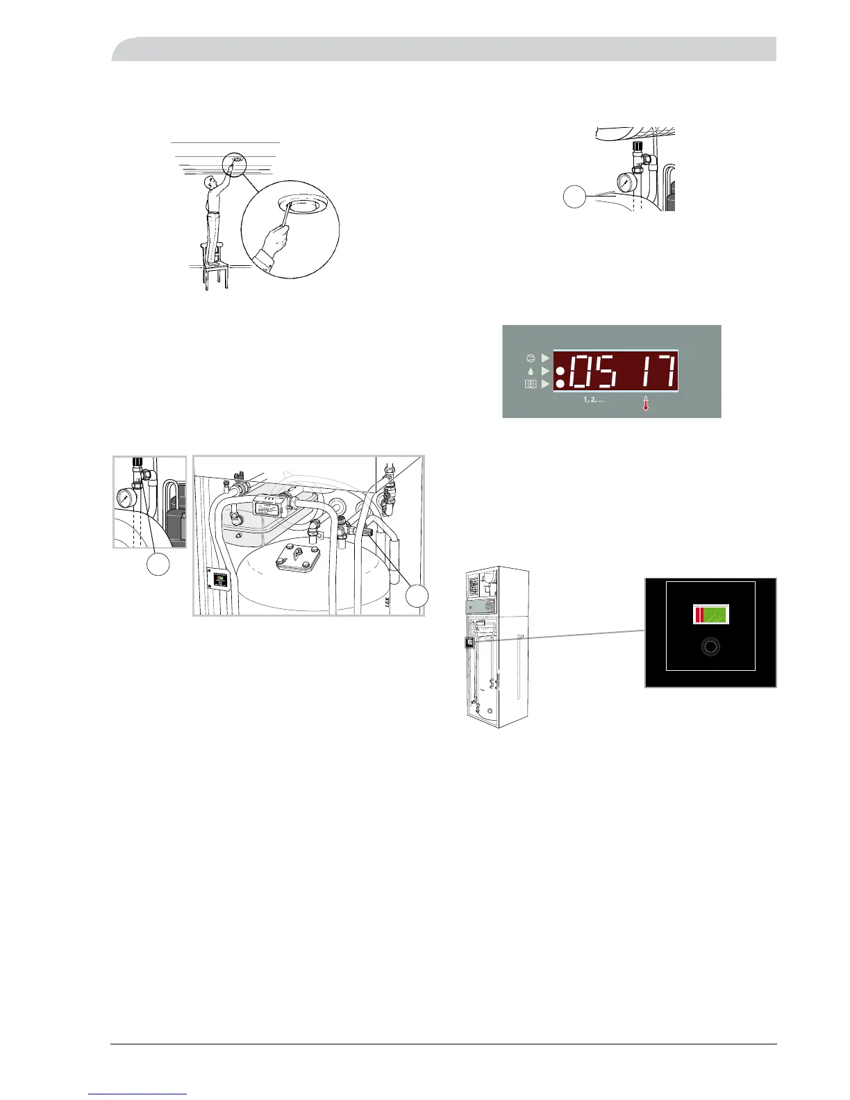
Pressure gauge
Pressure gauge (42) is located behind the upper service
cover. The pressure gauge reading should be between the
initial pressure of the expansion vessel and 2.5 bar (25
mvp). See “Commissioning and adjusting”.
Sacrificial anode test
The sacrificial anode should be checked regularly (at least
four times a year).
This is done by holding in the sacrificial anode test but-
ton. If the pointer remains in the red field the anode must
be changed immediately as the anode is spent and can no
longer fulfil its protection function.
Kesseldruck
R
0 Ausgeschaltet
1 Normalbetrieb
R Reservebetrieb
Achtung!
Kontrollieren Sie, daß der
Kessel vor Inbetriebnahme
gefüllt ist.
Kompressor in Betrieb
Enteisung läuft
Zusatzwärme in Betrieb
Blinkende Dioden:
Siehe Bedienungs-
anweisungen!
Kanal Wert
Verschiebung
der Wärmekurve
(Höhen/Senken der Wärme)
Wärmekurven-
wahl
155
10
+2-2
0
20
Umwälzpumpe
Zusatzwärme
Betriebsstufe
Druck (Kessel/Leitungssystem):
0,5 – 2,5 bar. Vor dem Einfüllen,
Bedienungsanleitungen kontrollieren
Rückstellen des Temperatur-
begrenzers
Rückstellen der Sicherung
1
0
0 Ausgeschaltet
1 Normalbetrieb: Sämtliche Steuerfunktionen eingekoppelt.
R Reservebetrieb: Wartung erforderlich. Die Wärme von Hand
mit dem Schunt regulieren.
Normale Ventilation.
Extra Warmwasser:
Erhöhung der Speichertemperatur.
Wiederholtes Drücken ergibt folgenden Betrieb:
– Erloschene Diode
– Leuchtende Diode
– Blinkende Diode
Betriebsstufe:
Leuchtende Diode indikiert Wahlfunktion.
Knopfdrücken für Änderung.
Kanalwahl
Regelmäßige Wartung von:
Luftfilter
Ventilator
Luftventilen
Sicherheitsventilen
Sicherheitsventile im Leitungssystem:
Regelmäßig bedienen durch Drehen des
Ventilgriffes gegen den Uhrzeigersinn.
Bei Bedarf System nachfüllen;
Siehe Bedienungsanleitungen!
Kanalwahl:
1 Kesseltemperatur
2 Vorlauf für Heizsystem
3 Außentemperatur
Blinkende Indikierungen:
A01 = Filterreinigung notwendig
A02 = (Gefierrisiko in Zuluftbatterie)
A03 = Kompressorschutz aktiviert
4 Verdampfungstemperatur
5 Fortlufttemperatur
6 Wärmekurvenwahl
7 Verschiebung der Wärmekurve
8 Temperatur für Kompressorfühler
9 (Zulufttemperatur)
10 Berechnete Vorlauftemperatur
11 Abweichung von Vorlauftemperatur
12 Service A
13 Service B
14 Service C
15 Service D
16 Service E
17 Service F
18 Service G
19 Service H
20 Service I
21 Service J
maxmin
: Normale Temperatur
: Erhöhte Temperatur während 24 Stunden
: Periodisch erhöhte Temperatur
Die Einstellung ist abhängig vom
Wärmesystemtyp sowie der
geographischen Lage.
Zwecks korrekter Einstellung den
Planer zu Rate ziehen.
Die Richtwerte sind in der Be-
dienungsanleitung aufgeführt.
Extra Warmwasser
Achtung!
In Betriebsstufe Ventilation
"Aus" hat man keine Wärme-
rückgewinnung.
Ventilation:
Erhöht
Normal
Aus
(blinkend)
(leuchtend)
(erloschen)
2
1
bar
3
04
T
G
0 0
1
R
ANODEN-TESTER
Kontrollknopf drücken
Rot:Anode austauschen