Dealing with malfunctions
Indications on the numerical display
Error code A - 01 on the numerical display
Indication that the air filter needs to be cleaned (error •
code is shown every third month).
When the filter has been cleaned reset the fault code by
turning the heat pump off and on again.
Error code A - 03 on the numerical display
A high pressure or low pressure pressostat in the refriger-
ant circuit has tripped, see the section “Resetting presso-
stats”.
High-pressure pressostat: Settings for “Heating curve •
selection” and “Heating curve offset” too high (can
also be seen on Channels 6 and 7 on the numerical
display). Also see section “Room temperature”.
Low-pressure pressostat: Ventilation flow too low or •
not enough refrigerant.
When the cause of the fault has been rectified, the error
code must be cleared from the display by switching the
heat pump off and on again.
Error code A - 05 on the numerical display
Stove monitor
External differential pressure monitor. Compressor and •
fan stop when the pressure difference between the
chimney and the stove’s installation area is too great
Fault code resets automatically when the pressure differ-
ence returns to normal.
Midmost lamp lit
Defrosting. •
When there is too much ice on the evaporator, defrost-
ing takes place. After this, the compressor starts auto-
matically if heating is needed. Frequent defrosting is a
sign of clogged ventilation or dirty filter. See the section,
“Maintenance routines” – “Cleaning the air filter”.
High extract air temperature
If the extract air temperature (read on channel 5) is only
insignificantly lower than the room temperature at the
same time as the compressor is operational, this indicates
a probable fault in the refrigerant circuit or its controller.
Request a service.
When the compressor is not operational the extract air
temperature lies at about the same level as the room tem-
perature.
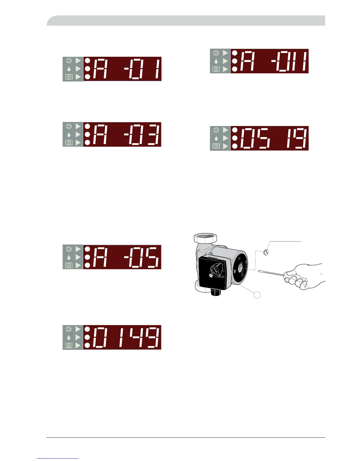
Help starting the circulation pump
Shut down FIGHTER 640P by turning the switch (8) to •
“0”.
The upper service cover is opened by pulling the lower •
section outwards. The cover can then be lifted off.
The inner cover is secured by a magnetic strip on the •
lower edge.
Loosen the venting screw with a screwdriver. Hold •
a cloth around the screwdriver blade as a certain
amount of water may run out.
Insert a screwdriver and turn the pump rotor.•
Screw in the venting screw.•
Start FIGHTER 640P and check whether the circulation •
pump runs.
It is usually easier to start the circulation pump with
FIGHTER 640P running, switch (8) set to “1”. If helping the
circulation pump to start is performed with FIGHTER 640P
running, be prepared for the screwdriver to jerk when the
pump starts.