Ventilation connection
Fan diagram
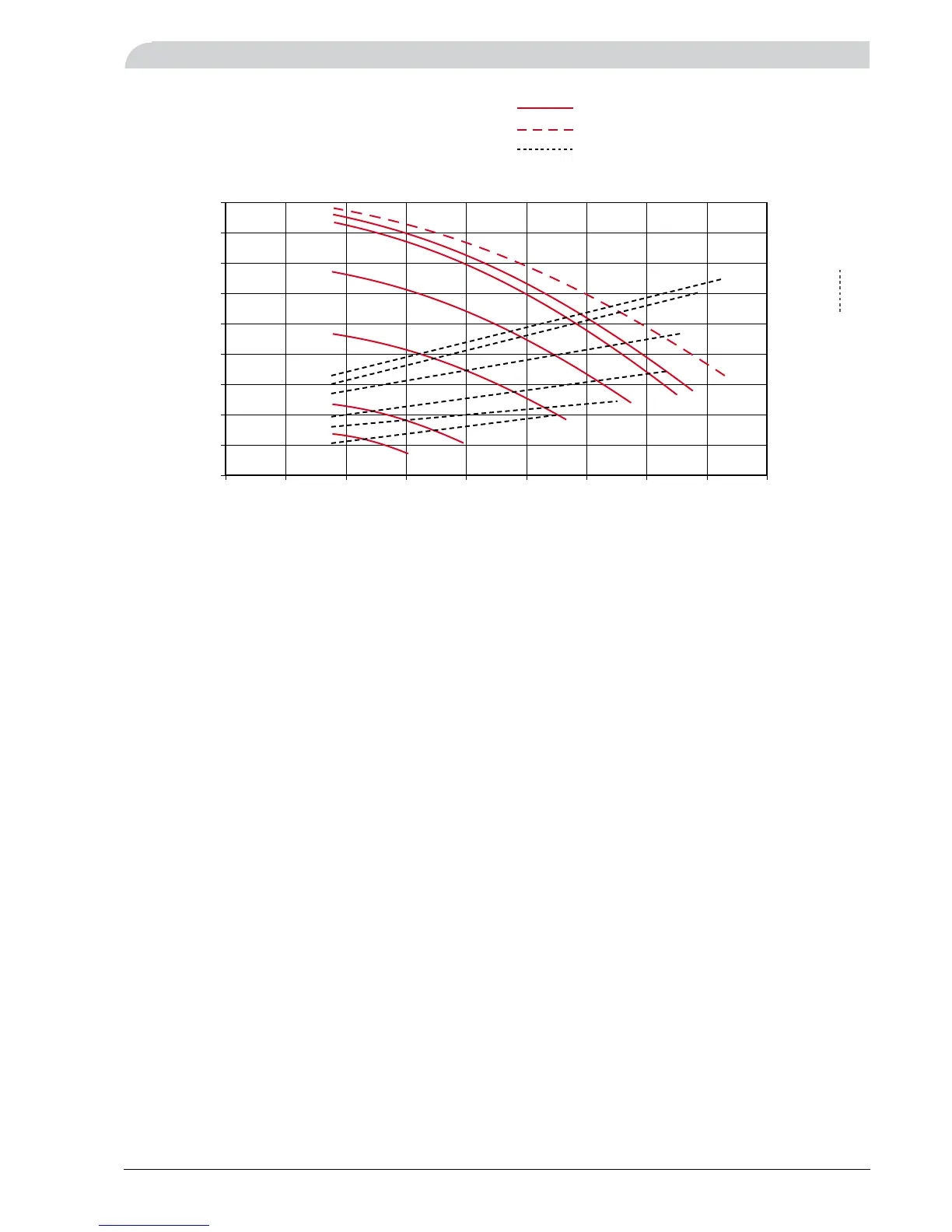
The diagram below shows the available ventilation capacity
as well as the supplied fan output. The numbering of the
curves refers to the graduation of the potentiometers.
Luftkapacitet på Prototyp F640P (extra tätningslist under luckan)
0
50
100
150
200
250
300
350
400
450
500
550
20
40
60
80
100
120
140
160
180
200
220
050 100 150 200 250 300 350 400
J
J
I
H
F
G
E
D
J
I
H
F
G
E
D
m
3
/h
l/s
0
50
100
150
200
250
300
350
400
450
20
40
60
80
100
120
140
160
180
050 100 150 200 250 300 350 400 450
E
E
F
F
G
G
H
H
I
I
J
J
J
Fläktdiagram utan effekt. Används i svenskt F640P produktblad.
0
50
100
150
200
250
300
350
400
450
050 100 150 200 250 300 350 400 450
E
F
G
H
I
J
J
0255075 100
Airflow (m
3
/h)
Available pressure, Pa
Air intake only through the exhaust air sleeve
Air intake through both the exhaust air and
extract air sleeves
Supplied fan output.
Fan output, W
Example, reading off the fan output
Requirements: Airflow 200 m
3
/h. Required pressure in-
crease (=pressure drop in duct system) 270 Pa.
To select curve:
Read off the cutting point between the desired airflow •
and required pressure increase.
Select the closest solid lined curve (in this case curve •
H).
To read off the fan output:
Look at the dotted line for the selected curve (in this •
case curve H), and read off the fan output on the
right-hand axis. In this instance, the fan output is 70
W at an airflow of 200 m
3
/h.
Exhaust air duct
The kitchen flue must not be connected to FIGHTER 640P.
Adjustment
See the section “Setting the ventilation”.