Pipe connections
Pipe connections
General
Pipe installation must be carried out in accordance with
current norms and directives.
The system requires a low-temperature design of the radia-
tor circuit. At DUT, the highest recommended temperatures
are 55 °C on the flow line and 45 °C on the return line.
When the circulation pump is running, the flow in the
radiator circuit must not be completely stopped. In other
words, in a system where the radiator flow might stop
because all thermostat valves are closed, there must be a
bypass valve to protect the circulation pump.
The total volume is 244 litres, with 189 litres in the water
heater and 55 litres in the boiler section.
The pressure vessel in the FIGHTER 640P is approved for
max 9.0 bar (0.9 MPa) in the water heater and 2.5 bar
(0.25 MPa) in the boiler section.
An overflow pipe should be routed from the safety valve to
an appropriate drain. The dimension of the overflow pipe
must be the same as the waste water pipe and be routed
downwards to prevent water pockets and to be frost proof.
Overflow water from the evaporator collection tray and
safety valves goes via non-pressurised collecting pipes to a
drain so that hot water splashes cannot cause injury.
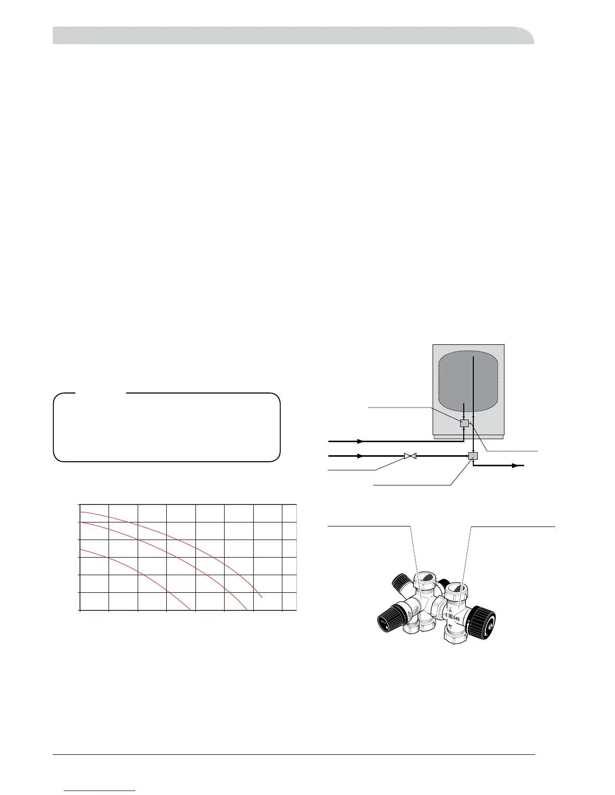
Pump diagram
The pipe work must be flushed before the
heat pump is connected, so that any con-
taminants do not damage the components
parts.
Note!
Flow l/h
Available pressure kPa
Hot and cold water are connected to pos (74) (hot water)
and (73) (cold water).
The attendant expansion vessel (107) must be connected
to the hot water system.
The heat pump should be supplemented with an electric
water heater if a bubble pool or other significant consumer
of hot water is installed.
If the heater is equipped with a valve connection Ø of
15 mm, this should be replaced with an equivalent (split) Ø
22 mm coupling.
Appropriate heaters are COMPACT 100-300 for floor-
mounting and EMINENT 35-100 for wall-mounting.
1. Split the valve coupling.
2. Attach the valve coupling section to the heater’s incom-
ing cold water.
3. Attach the mixing valve section to the heater’s outgoing
hot water.
4. Plug the split on the valve coupling section.