Commissioning and adjusting
Commissioning and adjusting
Preparations
Check that the switch (8) is set to “0”.
Check that valves (44) and (50) are fully open and that the
temperature limiter (6) has not tripped (press firmly on the
rubber membrane). Also check the operating thermostat’s
(3) settings (normally max).
Filling the hot water heater
The water heater is filled by first opening a hot water tap
and then opening the filling valve (46) fully. This valve
should then be fully open during operations. When water
comes out of the hot water tap this can be closed.
Filling the heating system
Remove the upper service cover so the pressure gauge •
(42) becomes visible.
Connect a hose to the filling valve (49) and open the •
valve to fill the boiler and the radiator system.
After a while the pressure gauge (42) will show rising •
pressure. When the pressure has reached about 2.5
bar a mix of air and water starts to emerge from the
safety valve (52). Close the filling valve (49).
Venting the heating system
Vent the electric boiler through the safety valve (52), •
venting screws (17), (59) and the rest of the heating
system through the relevant venting valves.
Keep topping up and venting until all air has been re-•
moved and the pressure is correct.
Starting
Set the switch (8) to “• ”. In this mode the elec-
tronics are disconnected, so the display window is not
lit. The thermostat (3) opens at 71°C in this mode.
When the room temperature exceeds 16°C set switch •
(8) to “1”. Note! The compressor has a start delay of
about 20 minutes.
Set the design capacity on the circulation pump using •
its switch (35). See the section “Pipe connections” –
“Pump and pressure drop diagram”. Make sure that
the switch is not in an intermediate position.
Readjustment
Air is initially released from the hot water and venting may
be necessary. If gurgling sounds can be heard from the
heat pump, the entire system will require additional vent-
ing. Note! Safety valve (52) also acts as a manual venting
valve. Operate it with care, since it opens quickly. When
the system is stable (correct pressure and all air eliminated)
the automatic heating control system can be set as re-
quired. See the section “Room temperature” – “Setting
the Automatic heating control system” and “Front panel”.
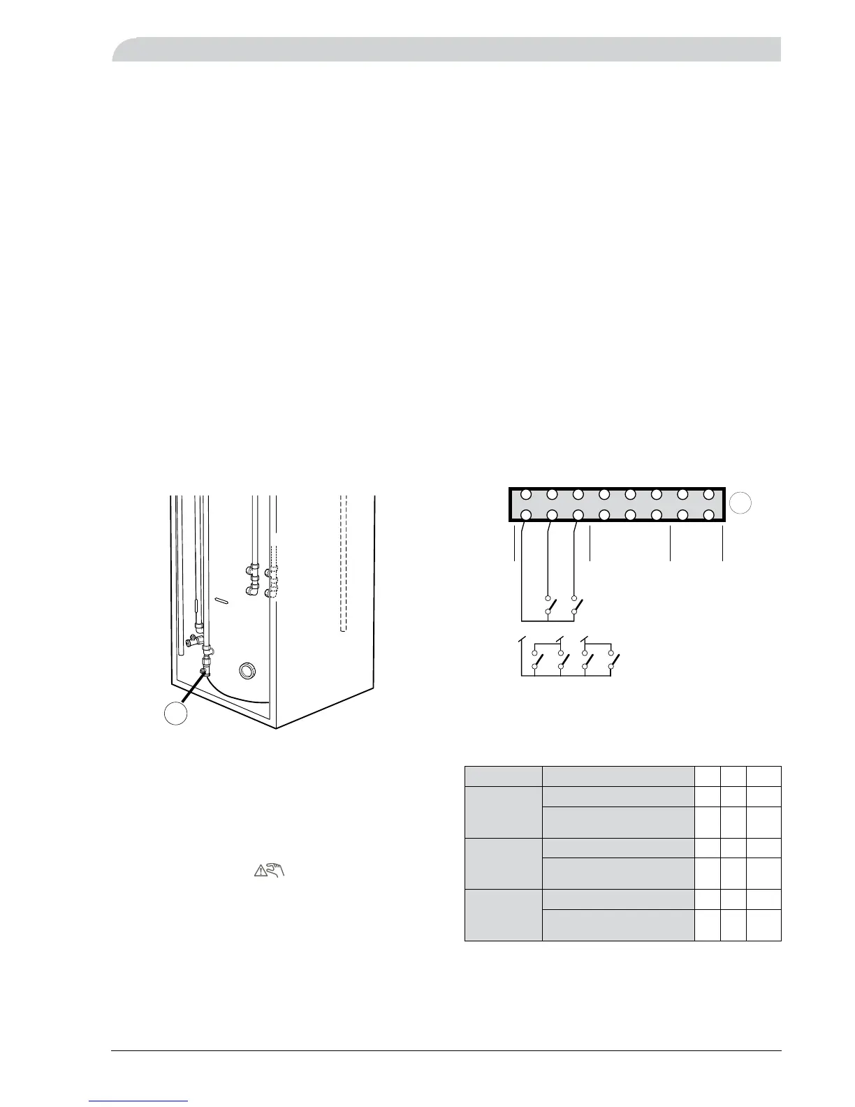
Centralised load control and load monitor
The output steps of the immersion heater can be discon-
nected by means of a load sensor or a centralised load
control relay. This is done with making contacts, connected
to terminal (14).
If both the load monitor and centralised load control are to
be used these are connected in parallel.
The table below describes output disabling:
A B A+B
Max power
output 6
kW
Max available output (kW) 6 3 0
Power disconnected (kW) 0 3 6
Max power
output 8
kW
Max available output (kW) 5 2 0
Power disconnected (kW) 3 6 8
Max power
output 9
kW
Max available output (kW) 6 3 0
Power disconnected (kW) 3 6 9