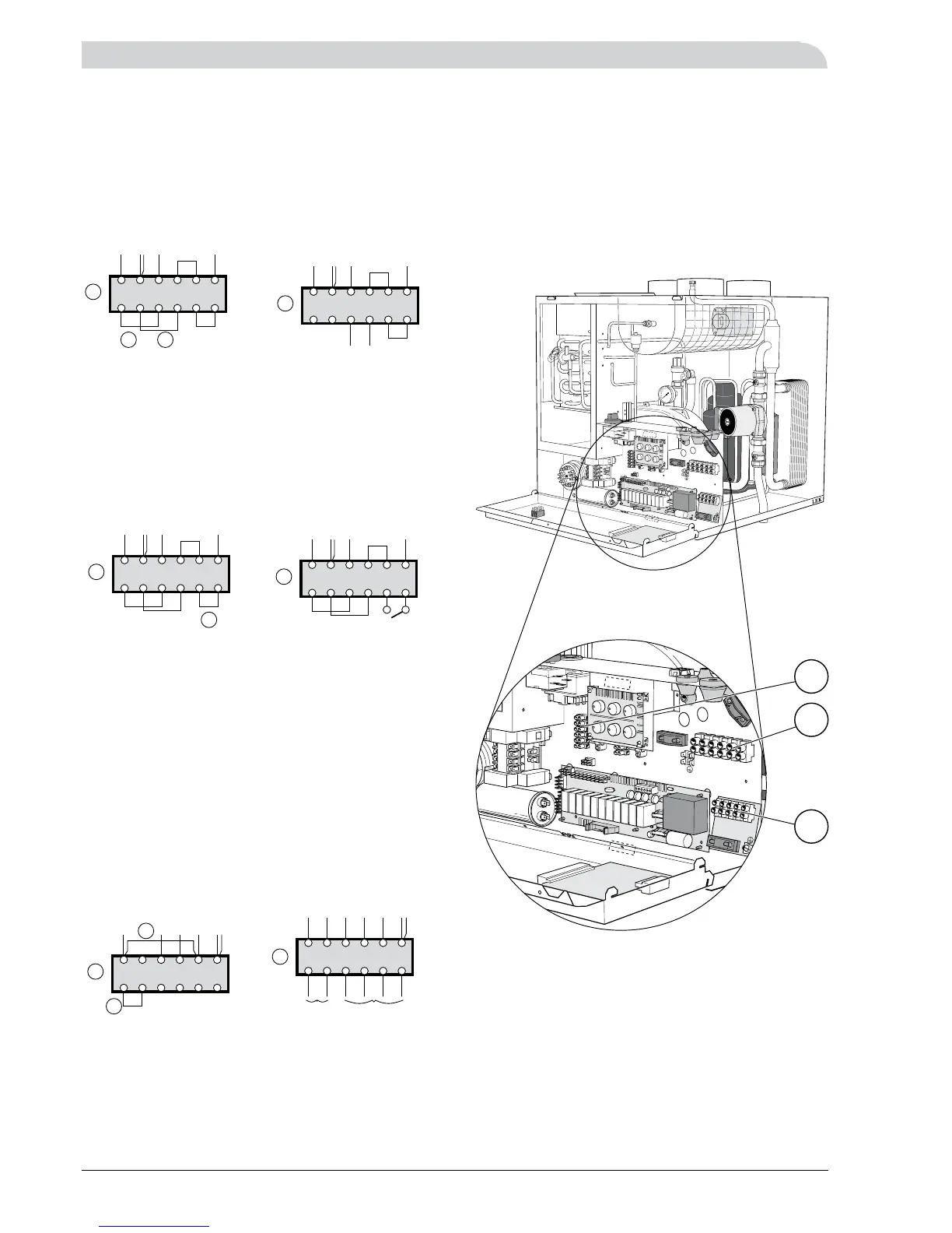
Electrical connections
External compressor control
The heat pump’s compressor can - if you wish - also be
controlled by an external switch by replacing strap C on
terminal block (12) with a potential free switch function
(230 V~, 6A, motor operation).
Note! In this position some parts of the electrical system
are live, even when the power switch (8) is set to “0”.
External compressor supply
The heat pump’s compressor can be externally fed if so
required by removing the straps A and B from terminal
block (12). The separate voltage supply (230 V~, 6A, motor
operation) is connected to “3” and “4”.
Note! In this position some parts of the electrical system
are live, even when the power switch (8) is set to “0”.
Separate supply to the immersion heater
Separate feed between the immersion heater and remain-
der can be obtained by making the following reconnec-
tions on terminal (9):
Remove straps D and E.•
Cable 037 between terminal block (13), terminal ”N” •
and relay card, terminal ”9” must be moved. Remove
the end from terminal block (13) and place it on termi-
nal block (9), terminal “1A”.
The immersion heater is now fed via terminal 9, pos •
“N-L1-L2-L3” and the remainder (compressor, circula-
tion pump, fan and control) are fed via terminal 9, pos
“1A-1B”.