EasyManua.ls Logo

Nice Apollo CBOX1K - User Manual

Nice Apollo CBOX1K
48 pages
Print Icon
To Next Page IconTo Next Page
Loading...
Nice Apollo Control
Box
Vehicular Gate Operator Control
Revision 1.0.0.0_6-2014
CBOX1K

Table of Contents

Question and Answer IconNeed help?

Do you have a question about the Nice Apollo CBOX1K and is the answer not in the manual?

Nice Apollo CBOX1K Specifications

General IconGeneral
BrandNice Apollo
ModelCBOX1K
CategoryControl Unit
LanguageEnglish

Summary

CAUTIONS AND NOTES

Extremely Important Safety Instructions

Emphasizes the need for thorough manual understanding before installation and operation.

UL325 Compliance Definitions

Defines terms related to vehicular gate operators and gates according to UL325 standards.

1 - OVERVIEW

1.1 1050 Control Board Overview

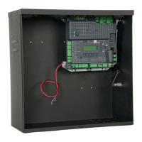
Describes the main control board, its features, connectors, and programming capabilities.

1.2 Control Board Specifics

Lists detailed specifications and features of the 1050 control board.

2 - GATE INFORMATION

Gate Latches and Specific Applications

Warns against manual latches and covers safety for specific gate applications.

General Requirements for Gate Systems

Covers safety, security, and maintenance needs for gate systems.

3 - SAFETY AND CAUTIONS

General Safety Warnings and Instructions

Provides critical safety instructions to reduce risk of injury or death during installation and use.

Gate System Safety Devices and Maintenance

Covers proper installation and maintenance of safety devices and system upkeep.

4 - INSTALLATION NOTES

Intended Usage and General Warnings

Specifies intended use and provides essential warnings for gate system installation.

5 - CIRCUIT BOARD LAYOUT

6 - INCOMING POWER WIRING

7 - CONTROL BOX MOUNTING

8 - NT-T51 K & NT-T71 K INSTALLATION

8.1 Parts Identification

Lists and identifies all components included for T5 and T7 actuators.

8.2 PIVOT ARM INSTALLATION

8.3 T5 ACTUATOR PIVOT BRACKET LOCATION GRAPH

8.4 T7 ACTUATOR PIVOT BRACKET LOCATION GRAPH

8.5 GATE BRACKET MOUNTING

8.6 ACTUATOR MOUNTING

8.7 ACTUATOR WIRING

8.8 LIMIT AND MOTOR CONNECTION TO THE BOARD

8.9 LIMIT SWITCH ADJUSTMENT

9 - 15501 K & 16501 K INSTALLATION

9.1 PARTS IDENTIFICATION

Lists and identifies all components included for 15501K and 16501K operators.

9.2 PULL TO OPEN INSTALLATION

9.3 PUSH TO OPEN INSTALLATION

9.4 ACTUATOR MOUNTING

9.5 ACTUATOR WIRING

9.6 GATE BRACKET MOUNTING

9.7 LIMIT AND MOTOR CONNECTION TO THE BOARD

9.8 LIMIT SWITCH ADJUSTMENT

9.9 SETTING THE LIMIT SWITCHES

10 - 35001 K & 36001 K INSTALLATION

10.1 PARTS IDENTIFICATION

Lists and identifies all components included for 35001K and 36001K operators.

10.2 POST INSTALLATION

10.3 CHASSIS MOUNTING

10.4 CONTROL ARM ASSEMBLY

10.5 GATE BRACKET MOUNTING

10.6 CHASSIS WIRING

10.7 LIMIT AND MOTOR WIRING

10.8 LIMIT AND MOTOR CONNECTION TO THE BOARD

10.9 SETTING THE LIMIT SWITCHES

11 LEARNING MODE

12 ACCESSORY INPUTS AND OUTPUTS

12.1 Accessory Outputs

Describes the function and programming of accessory outputs like OUT1, OUT2, Magnetic Lock, and Lamp.

12.2 Accessory Inputs

Explains various digital inputs for safety devices like loops, edges, fire, and guard stations.

12.3 Communication Buses

12.4 Programming Receivers and Remotes

13 120 VAC POWER WIRING

14 SOLAR PANEL CHART

15 OPTIONAL INPUTS

Fire Department Connection

Explains the dry contact input for fire department control and fail-safe connector.

Magnetic Lock Connection

Describes the connection for a magnetic lock to prevent forced opening.

Guard Station Inputs

Details guard station inputs for gate operation commands like Open, Stop, and Close.

Exit and Edge Wiring Diagram

Illustrates wiring diagrams for exit sensors and edge safety sensors.

15.5 Radio Receiver Connection

15.6 Optional Power Output

16 INSPECTION AND OPERATION

17 GENERAL LAYOUT AND SAFETY ACCESS

18 ACCESSORIES AND SENSORS

19 BOARD NOMENCLATURE

20 PROGRAMMING BUTTONS

20.1 Force Settings

Details how to set static and dynamic force sensitivity for gate operation.

20.2 Speed Settings

Explains settings for maximum, standard, and slow gate speeds and slowdown.

20.3 Acceleration Settings

Describes how to set gate acceleration limits for reversing and normal operation.

20.4 Delay Settings

Covers settings for auto-close, slave delay, lamp/strobe activation, and magnetic lock timing.

20.5 Function Programming

Explains programming for learn mode, positions, auxiliary inputs/outputs, and radio channels.

20.6 Display Information

Describes how to view system information like voltage, temperature, service history, and diagnostics.

21 EMERGENCY VEHICLE ACCESS

22 GLOSSARY

23 MAINTENANCE SCHEDULE

24 TROUBLESHOOTING

CONTROL BOX PARTS LIST

WARRANTY INFORMATION

INSTALLATION CHECKLIST