15
Tighten the wire terminals to complete the wiring connection
to the T5/T7. Re-attach the cover and secure with the
provided Phillips-head screws.
orange
green
white
blue
yellow
red
black
Connect T5 motor
cable to outlined
wire terminals
white
green
orange
blue
yellow
red
black
Connect motor
cable to outlined
wire terminals
T5 MOTOR WIRING
T7 MOTOR WIRING
1
2
3
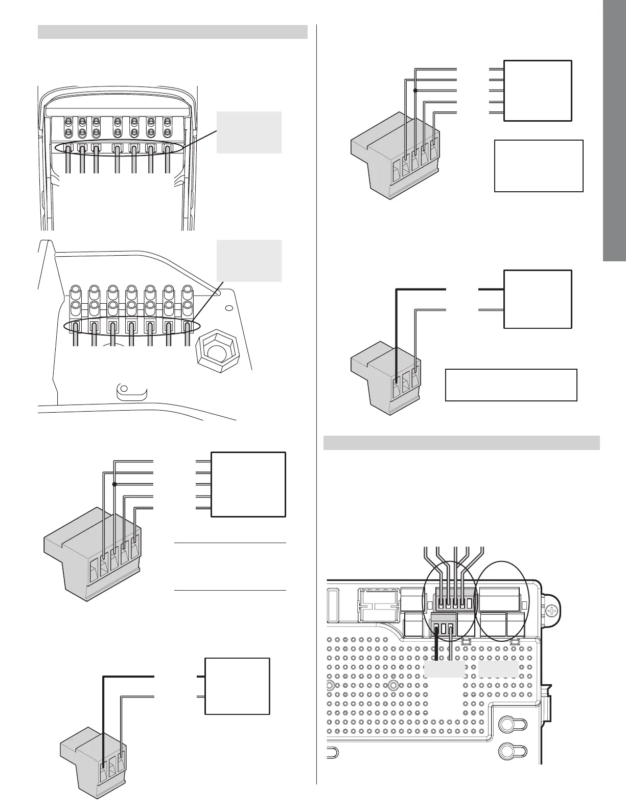
Connect the T5/T7 cable to the 5-pin connector as shown
below for pull to open installations
Connect the actuator motor leads to the 3-pin connector
as shown below. Note: If the gate moves in the opposite
direction from what is expected, reverse the actuator
wiring from what is shown. (Red to Pin 3, Black to Pin 1).
Install the 5 and 3-pin connector for motor 1 into the
connection labeled “Motor 1” on the controller as shown.
For a dual gate installation install the 5 and 3-pin and
connector for motor 2 into the connection labeled “Motor 2”.
Note: (Motor 1) - Make sure motor lead connector is plugged
in below the limit 5 pin terminal connector
T5 and T7
Limit and
Encoder wiring
T5 and T7
Motor wiring
green
yellow
blue
orange
white
red
black
green: limit common
yellow: motor encoder signal
blue: common
orange: open limit switch
white: close limit switch
MOTOR 2MOTOR 1
8.7 - ACTUATOR WIRING
8.8 - LIMIT AND MOTOR CONNECTION TO THE BOARD
Connect the T5/T7 cable to the 5-pin connector as shown
below for push to open installations.
Connect the T5/T7 motor leads to the 3-pin connector as
shown below. Note: If the gate moves in the opposite direc-
tion from what is expected, reverse the motor wiring from
what is shown. (Red to Pin 1, Black to Pin 3).
T5, T7
H12, M12
Limits and
Encoder
T5, T7
H12, M12
Motor Leads
White: Close limit
Orange: Open Limit
Green: Limit Common
Yellow: Encoder Signal
Blue: Encoder Power
NOTE: If gate moves in opposite
direction from what is expected,
reverse the motor power lead wiring
Green
Yellow
Blue
White
Orange
Black
Red
NT-T51K & NT-T71K INSTALLATION