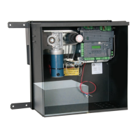
7251 / 7351 Slide Gate Operator
INSTALLATION AND PROGRAMMING MANUAL
28
11.1 HIGH VOLTAGE WIRE GAUGE REQUIREMENTS
TABLE 11-1: MAXIMUM RUN PER WIRE GAUGE
110V/AWG GAUGE 14 12 10 8 6 4
MAX RUN
180 FT
(54.8m)
280 FT
(85.3m)
460 FT
(140m)
700 FT
(213.3m)
1150 FT
(350.5m)
1800 FT
(548.6m)
Use Table below to determine high voltage wire size requirements. Distance shown in the chart is measured
from the operator to the power source. If power wiring is greater than the maximum distance shown, a service
feeder is recommended. When large gauge wire is used, a separate junction box must be installed for the
operator connection.
Wire table is based on stranded copper wire. Wire run calculations are based on a 110 VAC power source with
a 3% voltage drop on the power line, plus an additional 10% reduction in distance to allow for other electrical
losses in the system.
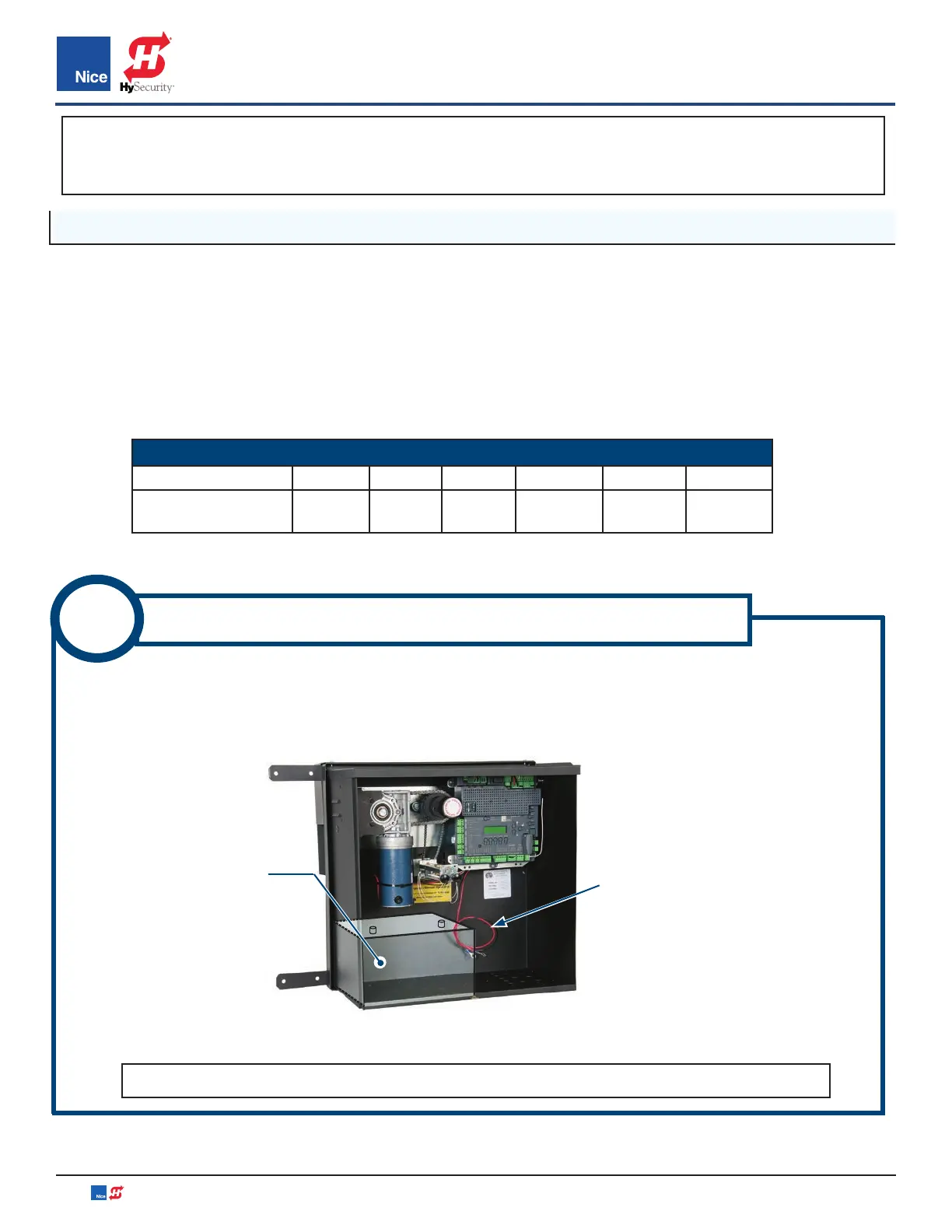
1. Locate the two battery leads (red & black with with battery lugs) inside unit (IMAGE 11-1).
2. Attach lugs of the battery cable to the battery terminals; black to negative (-) and red to positive (+)
terminals.
11
CONNECT BATTERY CABLES TO BATTERY
NOTE: LED below the terminal will glow red if battery is mis-wired.
IMAGE 11-1: BATTERY CABLES
IMPORTANT!
Power should not be applied to the control board until after the photo eyes have been installed
and wired to the control board. Power is applied in INSTRUCTIONS 12, 13, and/or 14.
BATTERY
BATTERY
CABLES
www.ApolloGateOpeners.com | (800) 878-7829 | Sales@ApolloGateOpeners.com