7251 / 7351 Slide Gate Operator
INSTALLATION AND PROGRAMMING MANUAL
19
5A
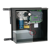
7251 - WIRE MOTOR TO CONTROL BOARD
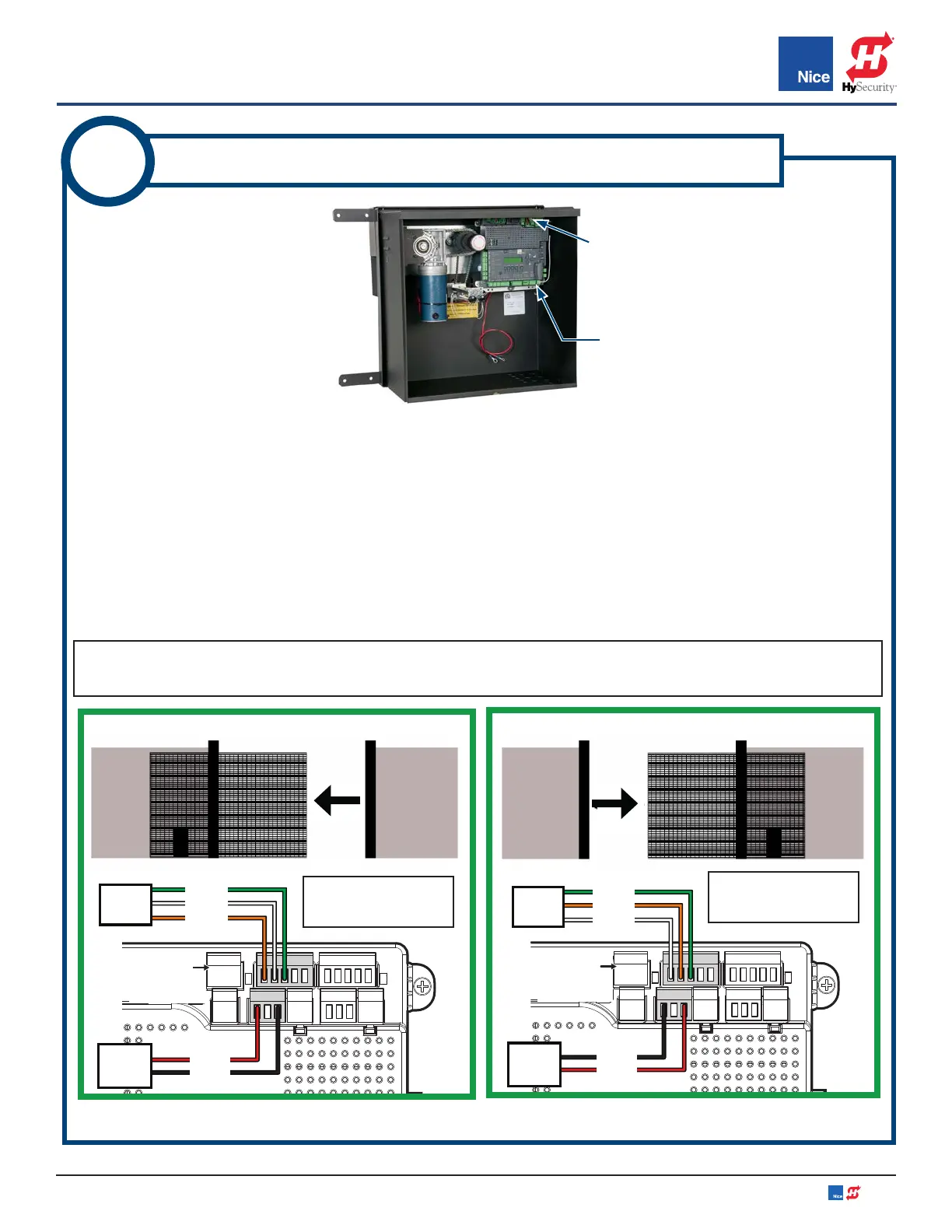
7251 - LEFT OPENING SINGLE GATE WIRING:
If gate opens to left (from secure side) refer to IMAGE 5A-1 and ensure 5-pin/3-pin connectors are plugged
into the “Motor 1” connectors (IMAGE 5A-1) and wired as shown.
7251 - RIGHT OPENING SINGLE GATE WIRING (DEFAULT):
If gate opens to right (from secure side) refer to IMAGE 5A-2, rewire connectors to match illustration, and plug
5-pin/3-pin connectors into the “Motor 1” connectors.
7251 - DUAL GATE WIRING:
If dual gate installation, refer to IMAGE 5A-3, rewire connectors to match illustration, then install 5-pin/3-pin
connectors for left-hand gate into “Motor 1” connection and the 5-pin/3-pin connectors for right hand gate
into “Motor 2” connection.
NOTE: If a gate moves in opposite direction from what is expected, reverse the motor power lead wiring
(red & black wires) for that motor.
NOTE: Gate view
is from secure side.
NOTE: Gate view
is from secure side.
L
o
r
WHITE
ORANGE
GREEN
DO NOT USE
RED
BLACK
MOTOR 1
WHITE: Close Limit
ORANGE: Open Limit
GREEN: Limit Common
7251
LIMITS
7251
MOTOR
LEADS
ORANGE
WHITE
GREEN
DO NOT USE
BLACK
RED
MOTOR 1
7251
LIMITS
WHITE: Close Limit
ORANGE: Open Limit
GREEN: Limit Common
7251
MOTOR
LEADS
IMAGE 5A-1: LEFT HAND SINGLE GATE WIRING IMAGE 5A-2: RIGHT HAND SINGLE GATE WIRING
MOTOR 1 MOTOR 1
OPEN
LEFT
OPEN
RIGHT
RIGHT HAND GATE (DEFAULT)
LEFT HAND GATE
1050 CONTROL
BOARD
1050 CONTROL
BOARD MOTOR
CONNECTIONS
www.ApolloGateOpeners.com | (800) 878-7829 | Sales@ApolloGateOpeners.com