FLASH
NO NONO NO
OGI
Bluebus
Stop SbS Open Close
HPSbS
FlashLight
Loop1
Master/Slave
Loop2
34
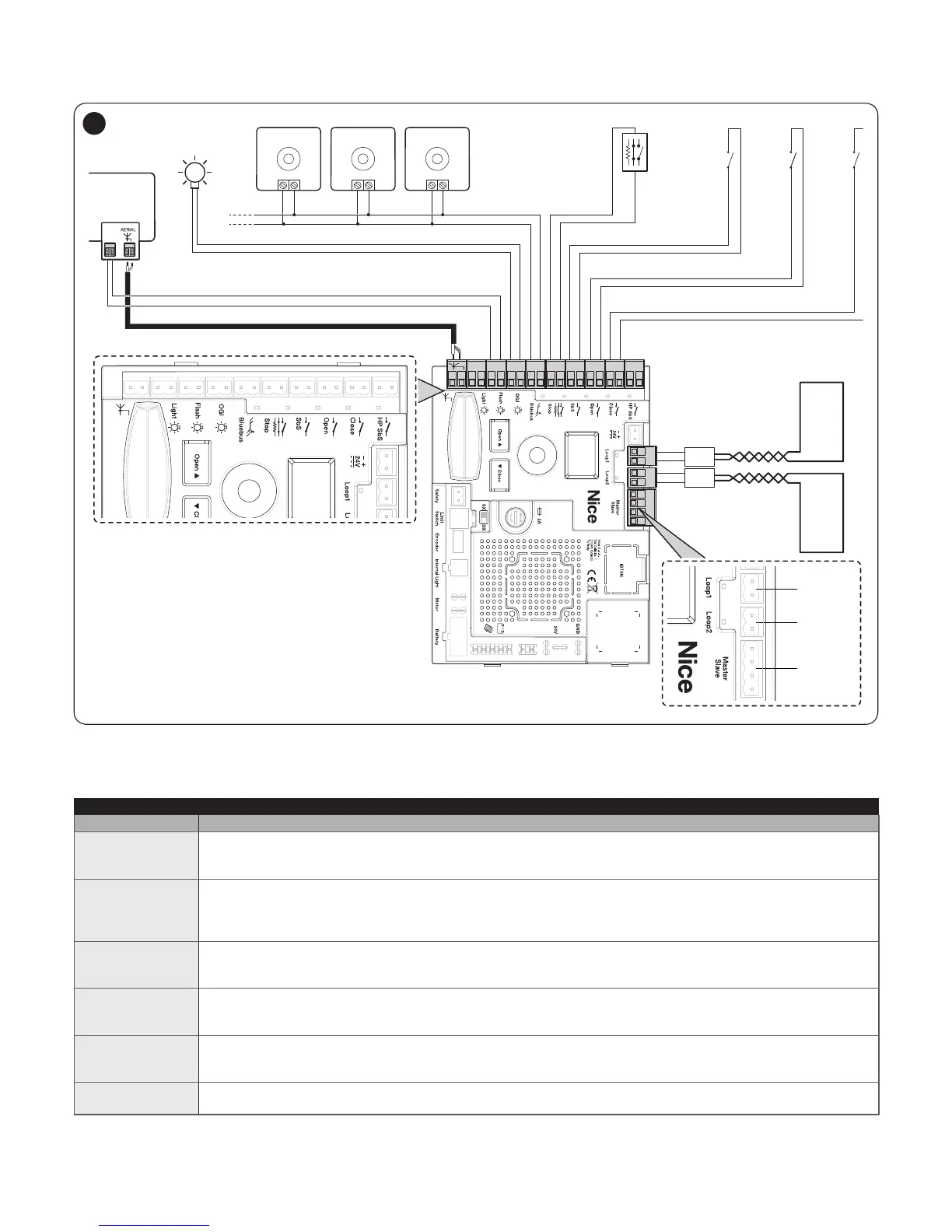
4.2.2 Description of connections
Table 4
ELECTRICAL CONNECTIONS
Terminals Description
LIGHT
output for “Boom Lights” warning light; it is possible to connect 24 V maximum 10 W warning devices.
It can also be programmed for other functions (refer to the “PROGRAMMING” chapter) or recongured through
the Oview programmer.
FLASH
Output for warning light; it is possible to connect 12 V max 21 W lamps or a Nice LUCY B, MLB or MLBT warning
light.
It can also be programmed for other functions (refer to the “PROGRAMMING” chapter) or recongured through
the Oview programmer.
OGI
“Open Gate Indicator” output; it is possible to connect a 24 V (maximum 10 W) signalling light.
It can also be programmed for other functions (refer to the “PROGRAMMING” chapter) or recongured through
the Oview programmer.
BLUEBUS
This terminal can be used to connect compatible devices, which are all connected in parallel with only two wires
carrying both the electric power and communication signals.
For further information on the BlueBUS, refer to the “BlueBUS” paragraph.
STOP
Input for devices that suspend or even stop the current manoeuvre; “Normally Closed” and “Normally Open”
contacts or xed resistor devices can be connected by suitably conguring the input.
For further information on the STOP function, refer to the “STOP input” paragraph.
SbS
Input for devices that control the movement in Step-by-Step mode; it is possible to connect “Normally Open”
contacts.
 Loading...


