30 – ENGLISH
Table 8
TROUBLESHOOTING
Problems Recommended checks
The radio transmitter does not
control the gate and the LED on the
transmitter does not light up
Check whether the transmitter batteries are exhausted and replace them if necessary.
The radio transmitter does not
control the gate but the LED on the
transmitter lights up
Check whether the transmitter has been memorised correctly in the radio receiver.
No manoeuvre is commanded
Check that the gearmotor is being powered with the mains voltage
Check whether fuses F1 and F2 are blown; if they are, identify the cause of the failure then
replace the fuses with others having the same current rating and characteristics.
No manoeuvre starts and the
warning light is off
Check that the command is actually received. If the command reaches the Step-by-Step
input, the corresponding “SbS” LED must light up; if instead the radio transmitter is used, the
“BlueBus” LED must emit two quick ashes.
No manoeuvre starts and the
warning light ashes a few times
Count the number of ashes and check the corresponding value in “Table 14”.
The manoeuvre starts but is
immediately followed by a reverse
run
The selected force could be too low for this type of boom. Verify that the boom is correctly
balanced and select a higher force, if necessary.
The manoeuvre is carried out at slow
speed
The manoeuvre does not start from one of the limit switches or the control unit does not learn
the limit switch.
Check the electrical connection of the limit switch.
The Slave barrier does not complete
the manoeuvres
Check that the “Master-Slave” learning phase was carried out on both barriers.
The manoeuvre is carried out in the
opposite direction
Check that the installation selector is in the correct position (see paragraph “Choosing the
direction“).
8.2 DIAGNOSTICS
The control unit contains the following diagnostics functions:
– signalling on the control unit through LED
– diagnostics through the display
– error signalling through the display
– warning light signals.
8.3 SIGNALS ON THE CONTROL UNIT
The LEDs near the control unit’s terminals issue special signals
to indicate both normal operation and any anomalies.
The following table describes the causes and solutions for each
type of signal.
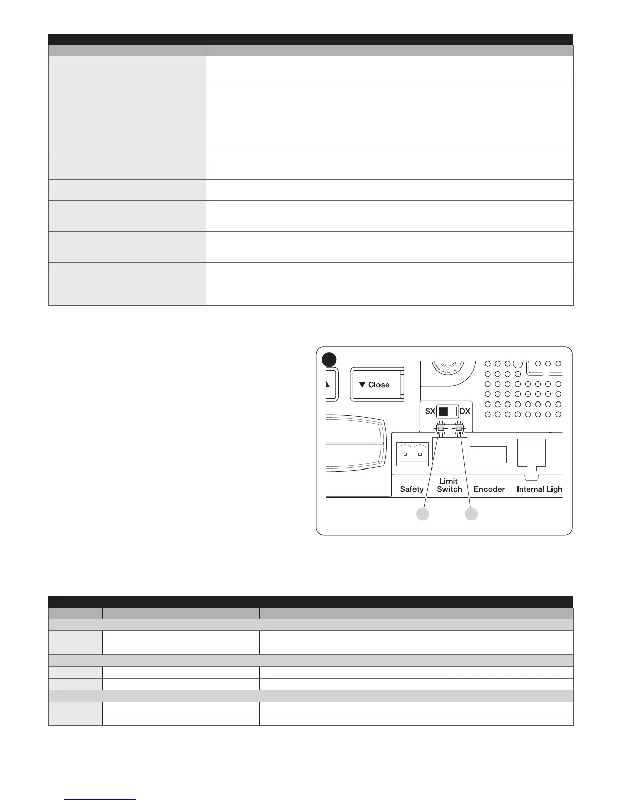
BA
44
A FC1 limit switch LED
B FC2 limit switch LED
Table 9
TERMINAL LEDS ON THE CONTROL UNIT
Status Meaning Possible solution
STOP LED
OFF
Intervention of the STOP input Check the devices connected to the STOP input.
On
Everything normal STOP input active.
Sbs LED
OFF
Everything normal Sbs input not active.
On
Intervention of the Sbs input This is normal if the device connected to the Sbs input is actually active.
OPEN LED
OFF
Everything normal OPEN input not active.
On
Intervention of the OPEN input This is normal if the device connected to the OPEN input is actually active
 Loading...


