ENGLISH – 19
5. verify the correct operation of all the safety devices pres-
ent, one-by-one (photocells, sensitive edges, etc.)
6. verify the correct operation of the photocells in the follow-
ing way:
– depending on whether one or two pairs of photocells
have been installed, one or two blocks of rigid ma-
terial (e.g. wooden panels) are required, measuring
70x30x20 cm. Each block must have three sides of re-
ective material (e.g. mirror or glossy white paint), one
for each dimension, and three sides of opaque material
(e.g. matt black paint). To test the photocells positioned
50 cm above the ground, the block must be placed on
the ground, or raised to 50 cm when testing photocells
positioned 1 m above the ground
– if the test is on a pair of photocells, the testing block
must be placed directly under the centre of the boom
with the 20 cm sides facing the photocells and moved
along the entire length of the boom
300
200
700
500
38
– if the test is on two pairs of photocells, the test must
rst be performed individually for each pair of photo-
cells using one testing block and then repeated using
two testing blocks; each testing block must be posi-
tioned laterally in relation to the centre of the boom, at
a distance of 15 cm and then moved along the entire
length of the boom
300
200
700
300
200
700
500
150
150
39
– during these tests, the testing block must be detected
by the photocells in any position it lies along the entire
length of the boom
7. check that there are no interferences between the photo-
cells and other devices:
– block the line of sight between the pair of photocells
with a cylinder (diameter 5 cm, length 30 cm), by mov-
ing it close to the TX photocell rst then next to the RX
photocell and then at the mid-point between the two
40
– check that the device intervenes in all cases, switching
from the active to the alarm status and vice-versa
– check that it triggers the intended action in the control
unit (e.g. a reversal of the movement during the closing
manoeuvre)
8. check on the safeguard against the lifting hazard: in
automations with vertical movement it is necessary to ver-
ify that there is no lifting hazard. This test can be carried
out in the following way:
– hang a 20 kg load (e.g. a sand bag) midway along the
boom’s length
– send an opening command and check that during the
manoeuvre the boom does not exceed a height of 50
cm above its closed position
– if the boom exceeds this height, the motor force must
be reduced (refer to the chapter “PROGRAMMING“)
9. if potentially dangerous situations due to the boom’s
movement have been prevented by limiting the impact
force, the latter must be measured according to the EN
12445 standard and, if the “motor force” control is used
to aid the system in reducing the impact force, it is neces-
sary to test various adjustments to nd the one that gives
the best results
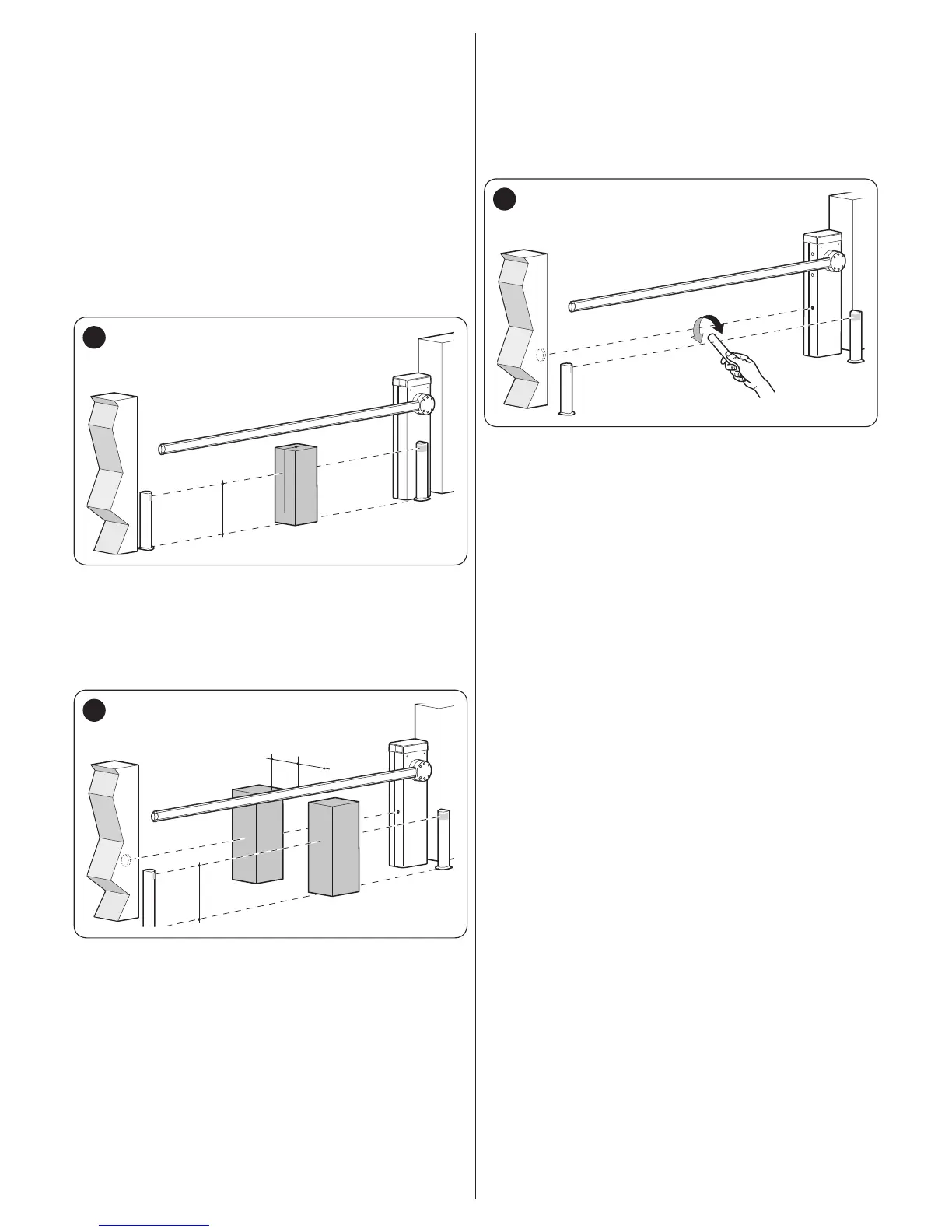
10. checking the efciency of the unlocking system:
– put the boom in the closed position and manually un-
lock it (see paragraph “Manually unlocking and lock-
ing the gearmotor“)
– verify that this occurs smoothly
– verify that the manual force to move the boom during
the opening phase does not exceed 200 N (roughly 20
kg)
– the force is measured perpendicularly to the boom at 1
m from the rotation axis
11. verication of the power supply disconnection sys-
tem: operate the power disconnection device and dis-
connect any available back-up batteries; check that all
the LEDs on the control unit are OFF and that the boom
remains stationary when a command is sent. Check the
efciency of the locking system to prevent any uninten-
tional or unauthorised connection.
 Loading...


