Mercury 310 Automated Gate System
Installation and Programming Manual
2020
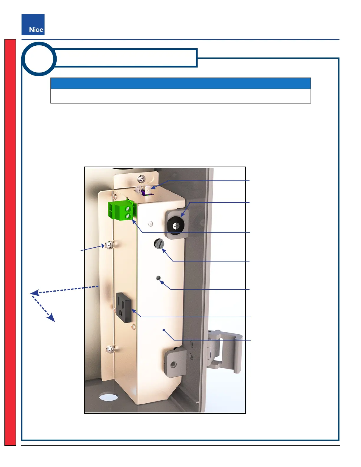
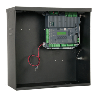
Power Led:
Lights up when DC power is
available. If o, check fuse.
Power Supply Module
Power Fuse:
(3A)
Panel Magnet:
Holds controller panel closed
Transformer Connector:
Factory wired to transformer
Service AC Outlet:
120 VAC power output
Power Connector:
Factory wired to Mercury
310 controller
STEP 2:
Loosen three
Screws
STEP 3:
Slide module left;
& pull out
1. Ensure all power sources are disconnected from the ACBOX310 and remove the battery leads from the
Mercury 310 controller.
2. Loosen the three screws indicated in image below.
3. Slide the power supply cover a little to the left to disengage the looseded screws from slots, then pull it
rearward out of the unit, being careful of existing wires and components.
NOTICE
The power supply module must rst be removed from the chassis before it can be wired.
Power Supply Module And Features
ACBOX310 Power Wiring
ACBOX310
3
(Continued)
www.ApolloGateOpeners.com | (800) 878-7829 | Sales@ApolloGateOpeners.com