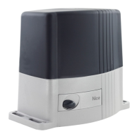
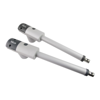
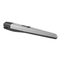
TITAN 912L Linear Actuator
Installation Reference Manual
1616
Antenna
Receiver
Close
GRD
OK
Open
Stop
Close
Open
+12V
Reset
BlueBus
GRD
+24V
N/C
COM
N/O
N/C
COM
N/O
GRD
GRD
12V
Alarm
Sol. Lock
Main Fuse
Limit 2
Encoder 2
Limit 1
Encoder 1
Motor 2Motor 1
3A
GRD
Reset
Edge
Safety
Shadow
Exit
UL
Fire
Input
GRD
GRD
GRD
GRD
GRD
GRD
GRD
GRD
GRD
+12V
Open
Input
USB
F/W Jumper
Learn
Input +12V a
Options
AutoClose
SlowDown
Force
Close
Stop
+12V
c
3A
b
c
Bypass 15A Fuse
A
A B
A B
B
Close
Close
Open
OpenOpen
COM
COM
Battery
Solar
3A
c
b
MOTOR 1
MOTOR 1
MOTOR 2
YELLOW
YELLOW
YELLOW
GREEN
GREEN
GREEN
BLUE
BLUE
BLUE
ORANGE
ORANGE
ORANGE
WHITE
WHITE
WHITE
BLACK
BLACK
BLACK
RED
RED
RED
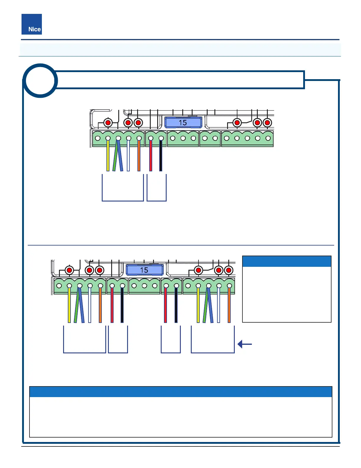
IMAGE 9B-2: 936 BOARD - PUSH-TO-OPEN - DUAL GATE
IMAGE 9B-1: 936 BOARD - PUSH-TO-OPEN - SINGLE GATE
9B
936 CONTROL BOARD WIRING: PUSH-TO-OPEN
5.2 936 CONTROL BOARD WIRING: PUSH-TO-OPEN
WIRE 2nd
ACTUATOR WITH
LONGER HARNESS
TO MOTOR 2
IMPORTANT!
For dual gate systems,
wire the 2nd harness into
the connector, but do not
connect it to the control board
yet. It will be connected at a
later step.
NOTICE
’ If gate moves opposite direction from expected, reverse red & black wires in that motor connector.
’ In dual gate systems, the longer actuator cable is usually conneted to MOTOR 2, but if the actuator
with longer cable has a shorter run time it may be connected to MOTOR 1 instead of MOTOR 2 if the
Gate Sync option is used.
www.ApolloGateOpeners.com | (800) 878-7829 | Sales@ApolloGateOpeners.com
 Loading...