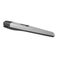
TITAN 912L Linear Actuator
Installation Reference Manual
2020
1. Open the actuator mechanical release, remove two torx 25 screws, and lift off cover.
2. Remove plastic cap covering the two adjustment wheels (IMAGE 10-1).
3. Press the CLOSE button on the control board. The gate should close until it hits the CLOSE limit
switch (LED = RED).
4. If the CLOSE limit is not acceptable (gate closed too far or not enough), re-open the gate partially
and then turn the turn the EXTEND Adjustment Wheel a few revolutions in “extend more” or “extend
less” direction as needed, then press CLOSE button on the Control Board again to check.
5. Check gate and repeat Steps 4-5 as necessary until CLOSE limit is acceptable.
6. Press the OPEN button on control board. The gate should open until it hits the OPEN limit switch
(LED = GREEN).
7. If the OPEN limit is not acceptable (gate open too far or not open all the way), re-close the gate
partially and then turn the RETRACT Adjustment Wheel a few revolutions in “retract more” or
“retract less” direction and press OPEN button on the Control Board again to check.
8. Check gate and repeat Steps 7-8 as necessary until OPEN limit is acceptable.
9. When nished, replace plastic cap on switches, afx actuator cover with two screws, engage
mechanical release, and lock.
10A
SETTING ACTUATOR FINE LIMITS: PULL-TO-OPEN
After installation of the control box (per separate installation instructions), the rst operation to perform after the
board has scanned for monitored safety devices is to ensure the open and close limits are acceptable. Refer
to INSTRUCTION 10A or 10B to determine open and close limits. To “teach” limits to the control board, see
seperate control box installation manual.
SECTION 6: SETTING ACTUATOR FINE LIMITS
IMPORTANT: DUAL GATE SYSTEMS!
To set the ne limits for two TITAN 912L actuators in a dual gate syatem:
1. Plug in only the primary actuator to MOTOR 1 input.
2. Determine limits for primary actuator per INSTRUCTION 10A or 10B (below).
3. Unplug primary actuator from the Motor 1 input.
4. Plug in secondary actuator to MOTOR 2 input.
5. Repeat steps in INSTRUCTION 10A or 10B for the secondary actuator.
6. When nished, plug primary actuator back onto MOTOR 1 input.
IMPORTANT!
The actuator key MUST be left with the customer. The key is necessary to use the mechanical release of
the actuator if the gate must be manually opened in the event of loss of power.
www.ApolloGateOpeners.com | (800) 878-7829 | Sales@ApolloGateOpeners.com
 Loading...