EN
2 – English
3.1 - Pre-installation checks
Before going ahead with the installation, check the integrity of the product com-
ponents, and ensure the model chosen is suitable for its intended use and for
the environment in which it is to be installed.
• Check that all the material to be used is in excellent condition and suitable for
its intended use.
• Check that the ground-mounted mechanical stops (not supplied), are present
both when opening and closing the automation system.
• Check that the mechanical structure of the gate is suitable for the installation
of automation and compliant with locally applicable regulations (if necessary,
refer to the label on the gate). This product cannot be used to automate a
gate which is not already in good, safe working order, neither can it fix faults
caused by incorrect installation or poor maintenance of the gate.
• Check that the operating conditions of the devices are compatible with the
usage limitation declared (see paragraph 3.2).
• Move the gate leaves manually in both directions and ensure that the resist-
ance to movement is constant at all points of travel (there should not be any
points where more force or less is required).
• Bring the gate leaves manually into a position at random, then let go and
check that they remain stationary.
• Check that the gearmotor fixing zone is compatible with its overall dimen-
sions (fig. 1).
• Check that the place where the gearmotor is to be installed allows enough
space for its arm to execute its full range of movement.
• Check that there is sufficient room around the gearmotor for it to be released
manually when required.
• Ensure that the surfaces on which the various devices are to be installed are
strong and capable of ensuring a firm hold.
• Ensure that each device is installed in a position which is protected and does
not expose it to accidental impacts.
• Ensure that all the electrical cables to be used are the type listed in Table 1.
3.2 - Usage limitation
Before installing the gearmotor, check that its data complies with the usage lim-
itation specified below and falls within the limits stated in the chapter entitled
“Product technical specifications”:
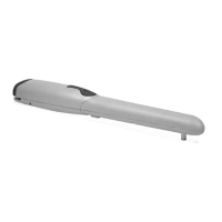
With FULL LENGTH motor arm (as shipped from the factory)
:
- maximum width of leaf: 1,80 m (= maximum weight of leaf: 100 kg)
- maximum height of leaf: 2 m
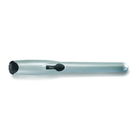
With SHORTENED motor arm (cut by the installer)
:
- maximum width of leaf: 1,60 m (= maximum weight of leaf: 100 kg)
- maximum height of leaf: 2 m
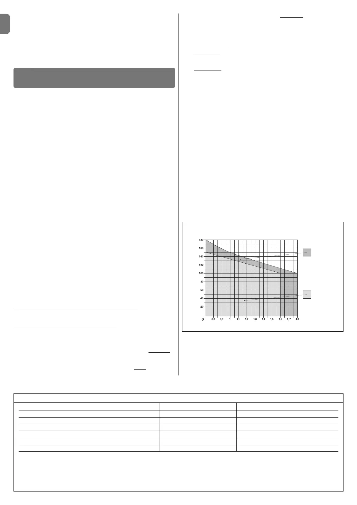
• Check to run: apply to Graph 1 the weight and width of the leaf; plot two lines
from these points and check that they intersect in one of the two grey areas
of
the graph. Important! - If the lines cross in the white area, this product cannot
be used to automate this particular gate.
• To enable the installation of the gearmotor, the minimum width
of the column
should be 80 mm.
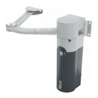
• The gearmotor arm must be positioned in the upper part
of the gate leaf.
IMPORTANT! - The gearmotor must not be mounted upside down, i.e. with
the arm pointing downwards.
• The arm’s fastening bracket must be fitted at one of the strongest parts of the
leaf (e.g. the frame), in order to ensure a firm and safe hold;
• Check distance
“E” (fig. 7):
- If distance
“E” falls in the range 80 mm (minimum) to 299 mm (maximum),
the gearmotor arm will need to be shortened. In such conditions, the leaf will
be able to open by up to 90°.
- If distance “E” is 300 mm or more, there is no need to shorten the gear-
motor arm. In such conditions, the leaf will be able to open by up to 110°.
3.3 - Preparatory work prior to installation
Fig. 2 illustrates an example of an automated system, achieved using Nice
components (some components may not be included in the kit):
a - Gearmotor with control unit mod. WL1024C
b - Gearmotor without control unit mod. WL1024
c - Multi-purpose lamp mod. WLT (to be installed on the gearmotor with con-
trol unit mod. WL1024C); see chapter 3.5 and the lamp’s own instruction
manual
d - Pair of photocells mod. MOFB
e - Digital keyboard (mod. MOTB) - Transponder reader (mod. MOMB) - Key
selector (mod. MOSE)
f - Pair of photocell posts
g - Opening and Closing mechanical stops
h - Electrical lock
These components are positioned according to a typical standard layout.
Referring to fig. 2, establish the approximate position in which to install each
component required for the system. Important – Before commencing installa-
tion, prepare the electrical cables necessary for your system, referring to fig. 2a
and to “Table 1 - Technical characteristics of the electrical cables”.
Important – While laying the tubes for the electrical cables, consider that due
to the possible build-up of water in the aqueducts, the connection tubes could
cause condensation to form inside the control unit and damage the electronic
circuits.
INSTALLATION
3
Connection Type of cable Maximum permitted length
A: POWER cable One 3 x 1.5 mm
2
cable 30 m (note 1)
B: ELECTRICAL LOCK cable One 2 x 1 mm
2
cable 6 m
C: BLUEBUS DEVICES cable One 2 x 0.5 mm
2
cable 20 m (note 2)
D: KEY SELECTOR cable Two 2 x 0.5 mm
2
cables (note 3) 50 m
E: GEARMOTOR POWER cable One 3 x 1.5 mm
2
cable 6 m
EXTERNAL AERIAL cable (optional) One type RG58 screened cable 20 m (recommended less than 5 m)
Note 1 – If the power cable is more than 30 m long, you will need to use a cable with a wider cross-section (3 x 2.5 mm
2
) and you will have to install protec-
tive earthing near the automation system.
Note 2 – If the Bluebus cable is more than 20 m long, and up to a maximum of 40 m long, you will need to use a cable with a wider cross-section (2 x 1 mm
2
).
Note 3 – These 2 cables can be replaced with 1 single 4 x 0.5 mm
2
cable.
IMPORTANT! – The cables used must be suitable for the type of environment where they are installed.
TABLE 1 - Technical characteristics of the electrical cables
GRAPH 1
For full length
arm
For shortened
arm
WIDTH (m.)
WEIGHT (kg.)
Other available accessories include the receivers designed with “SM” connec-
tors (SMXI, OXI, etc.).
The gearmotor with control unit (mod. WL1024C) is designed to accommodate
the installation of the multi-purpose lamp mod. WLT (see chapter 3.5), which
can operate as a flashing emergency light or courtesy light, depending on the
control unit programming. In addition, it can be used as a twilight by activating
a built-in light sensor; please refer to the relevant instruction manual for specifi-
cations.
 Loading...