EN
6 – English
4.5 - Addressing the photocells and other BlueBus devices
To allow the control unit to recognise the photocells connected to the Bluebus
system, these need to be addressed: correctly position the electric jumper of
each device, as shown in fig. 31.
To address other devices, refer to the respective instruction manual.
4.6 - Initialisation and connection check
Once you have powered the control unit, carry out the following checks:
• after a few seconds, check that the “Bluebus” LED (fig. 26) flashes regularly
at a frequency of 1 flash per second;
• check that the LEDs of the photocells, both TX and RX, emit flashes. The type
of flashing emitted, at this stage, is not significant;
• check that the WLT multi-purpose lamp is turned off (set on flashing function)
and connected to the FLASH output on the power supply.
If this does not happen, cut off the electricity supply to the control unit and
check the various electrical connections previously carried out.
4.7 - Recognition of the connected devices
Once initialisation is complete, the control unit must recognise the devices con-
nected to the “Bluebus” and “Stop” inputs.
IMPORTANT! – The recognition phase must be carried out even if the
con trol unit is not connected to any devices.
The control unit is designed to recognise individually the various devices con-
nected to it thanks to the recognition procedure and it can also detect with a
very high degree of precision any possible problems. Consequently, the recog-
nition of devices must be carried out each time a device is connected or
removed.
LEDs “L1” and “L2” on the control unit (fig. 26) emit slow flashes to indicate
that recognition needs to be carried out:
01. Press and keep pressed keys “” and “Set” (fig. 26) simultaneously.
02. Release the keys when LEDs “L1” and “L2” begin to flash quickly (after
approximately 3 seconds).
03. Wait a few seconds for the control unit to complete the device recognition
phase.
04. At the end of this phase, the “Stop” LED should be turned on and LEDs
“L1” and “L2” should turn off (LEDs “L3” and “L4” may start to flash).
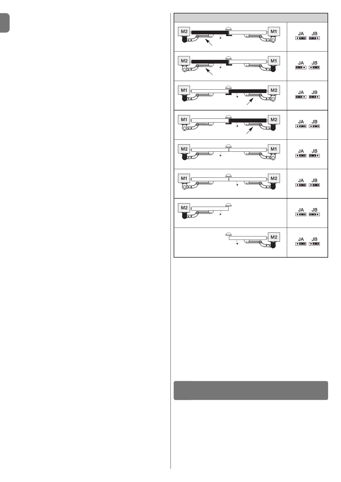
4.8 - Recognition of the positions of the mechanical stops
After the recognition of devices (paragraph 4.7), the control unit must recognise
the positions of the mechanical stops (maximum Opening and maximum Clo-
sure);
During this phase, the angle of aperture of the leaf is detected from the closing
mechanical stop to the opening mechanical stop. It is vital that the me -
chanical stops are fixed and sufficiently sturdy.
01. Identify the figure corresponding to your system in Table 2, fix the electric
jumpers JA and JB in place on the control unit, in the position as indicated
in this figure.
02. Release the gearmotors with the dedicated keys (see chapter 3.8) and
bring the leaves to their midpoint of travel so that they are free to open and
close; then secure the gearmotors.
03. On the control unit, press and keep keys “Set” and “” pressed simulta-
neously;
04. When LEDs “L3” and “L4” begin to flash quickly, (after approximately 3
secs.) release the keys;
05. Check that the automated system performs the following sequences of
manoeuvres:
a - Slow closure of gearmotor M1 to the mechanical stop
b - Slow closure of gearmotor M2 to the mechanical stop
c - Slow opening of gearmotor M2 and gearmotor M1 to the mechanical
stop
d - Complete quick closure of gearmotors M1 and M2
• If the first manoeuvre of one or both leaves is not a closing movement,
press any key to halt the recognition phase and check the positioning of
electric jumpers JA and JB referring to Table 2; otherwise, check the polar-
ity of the motor without control unit (mod. WL1024).
• If the first motor to start the closing movement is not M1, press any key
to halt the recognition phase and check the positioning of electric jumpers
JA and JB, referring to Table 2.
• If a device is activated during the recognition phase (photocells, key
selector, pressing of a key, etc.), the recognition phase is immediately halt-
ed. It must be repeated in full.
06. At the end of the closing manoeuvre of both motors (d), LEDs “L3” and
“L4” switch off to indicate that the procedure was completed successfully.
4.9 - Gate leaves motion check
At the end of the recognition of the positioning of the mechanical stops, we rec-
ommend you make the control unit perform a few opening and closing
manoeuvres, in order to ensure the gate moves correctly, to check for any
assembly and adjustment defects or other problems:
01. Press the Open key (fig. 26) and check that the Opening manoeuvre
includes an acceleration phase, a phase at constant velocity, a decelera-
tion phase and that the leaves stop against the opening mechanical end
stop.
02. Press the Close key (fig. 26) and check that the closing manoeuvre
includes an acceleration phase, a phase at constant velocity, a decelera-
tion phase and that the leaves stop against the closing mechanical end
stop.
03. Check, during manoeuvres, that the flashing performs certain flashes at 0.5
second intervals with the flashing on and 0.5 seconds with the flashing off.
These are the most important phases in the installation of the automation sys-
tem, in order to guarantee maximum system safety. Testing can also be used to
check the devices in the automation system regularly. The automation system
testing and commissioning phases must be carried out by qualified experts
who must be responsible for determining the tests necessary to check the
solutions adopted vis-à-vis the risks involved, and to check the observance of
all legal and regulatory obligations: in particular all the requirements of the EN
12445 standard which sets forth the test methods for checking automated
gates.
Additional devices must undergo specific testing, both in terms of functionality
as well as their correct interaction with WALKY; please refer to the relevant indi-
vidual instruction manuals.
TESTING AND COMMISSIONING
5
Overlapping leaf
Overlapping leaf
Overlapping leaf
Overlapping leaf
Control unit
Control unit
Control unit
Control unit
Control unit
Control unit
Control unit
Control unit
TABLE 2
 Loading...