Unidrive M / HS Frame 7 to 10 Power Installation Guide 25
Safety information Product information
Mechanical installation
Electrical installation Technical data UL listing information
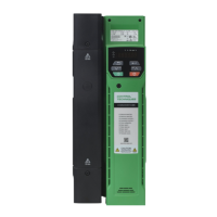
3.3 Terminal cover removal
3.3.1 Removing the terminal covers
Figure 3-3 Location and identification of terminal covers
Isolation device
The AC and / or DC power supply must be disconnected from the drive using an approved
isolation device before any cover is removed from the drive or before any servicing work
is performed.
Stored charge
The drive contains capacitors that remain charged to a potentially lethal voltage after the
AC and / or DC power supply has been disconnected. If the drive has been energized,
the power supply must be isolated at least ten minutes before work may continue.
Normally, the capacitors are discharged by an internal resistor. Under certain, unusual
fault conditions, it is possible that the capacitors may fail to discharge, or be prevented
from being discharged by a voltage applied to the output terminals. If the drive has failed
in a manner that causes the display to go blank immediately, it is possible the capacitors
will not be discharged. In this case, consult Nidec Industrial Automation or their authorized
distributor.
7
AC / DC
terminal cover
Motor / Braking
terminal cover
Control terminal
cover
AC
terminal cover
Motor / Braking
terminal cover
Control terminal
cover
9A 9E 10E
AC / DC
terminal cover
Motor / Braking
terminal cover
Control terminal
cover
8