Unidrive M/HS Frame 5 to 6 Power Installation Guide 41
Issue Number: 9
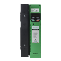
Safety information Product information
Mechanical installation
Electrical installation Technical data UL listing information
3.10 Internal braking resistor
Size 5 has been designed with an optional space-saving heatsink mounted resistor. The resistor can
be installed within the heatsink fins of the drive. When the heatsink resistor is used, an external
thermal protection device is not required as the resistor is designed such that it will fail safely under
any fault conditions. The in-built software overload protection is set-up at default to protect the
resistor. The resistor is rated to IP54 (NEMA 12).
Figure 3-17 Brake resistor installation on size 5
• Remove the terminal covers.
• Remove the brake resistor bung (1) from the hole in the chassis, the closed end of the bung will
need to be pierced so that the cable has access to be routed through.
• Feed brake resistor bung onto outer insulation of brake resistor cable. The wider end of the bung
should be inserted first. The Narrow end should align with end of insulation.
• Install the braking resistor to the heatsink using the captive screws. The screws should be
tightened to a maximum torque of 2 N m (1.5 lb ft).
• Route the cables through the provided hole at the rear of the heatsink as shown in Figure 3-17
and take the cable out from the front side of the drive. Ensure the cables are routed between the
fins of the heatsink, and the cables are not trapped between the heatsink fins and the resistor.
• Crimp the cable ends and make appropriate connections. The brake terminals must be tightened
to a maximum torque of 2 N m (1.5 Ib ft).
• Replace the terminal covers on the drive, tighten to a maximum torque of 1 N m (0.7 lb ft).
3.10.1 External brake resistor
External brake resistors are available for drive sizes 5 to 6. They can be mounted in the enclosure as
per mounting recommendation in Figure 3-11 Enclosure layout on page 32 using mounting brackets
part number 6541-0187. Figure 3-18 shows the brake resistor mounted on the mounting bracket.
Two M4 screws and nuts (2) can be used to fix the brake resistor to the mounting bracket. One M4
nut with washer (1) is provided to use for the ground connection. The brake resistor is equipped with
a thermal switch, the thermal switch should be integrated in the control circuit by the user.