Unidrive M/HS Frame 5 to 6 Power Installation Guide 95
Issue Number: 9
Safety information Product information Mechanical installation Electrical installation
Technical data
UL listing information
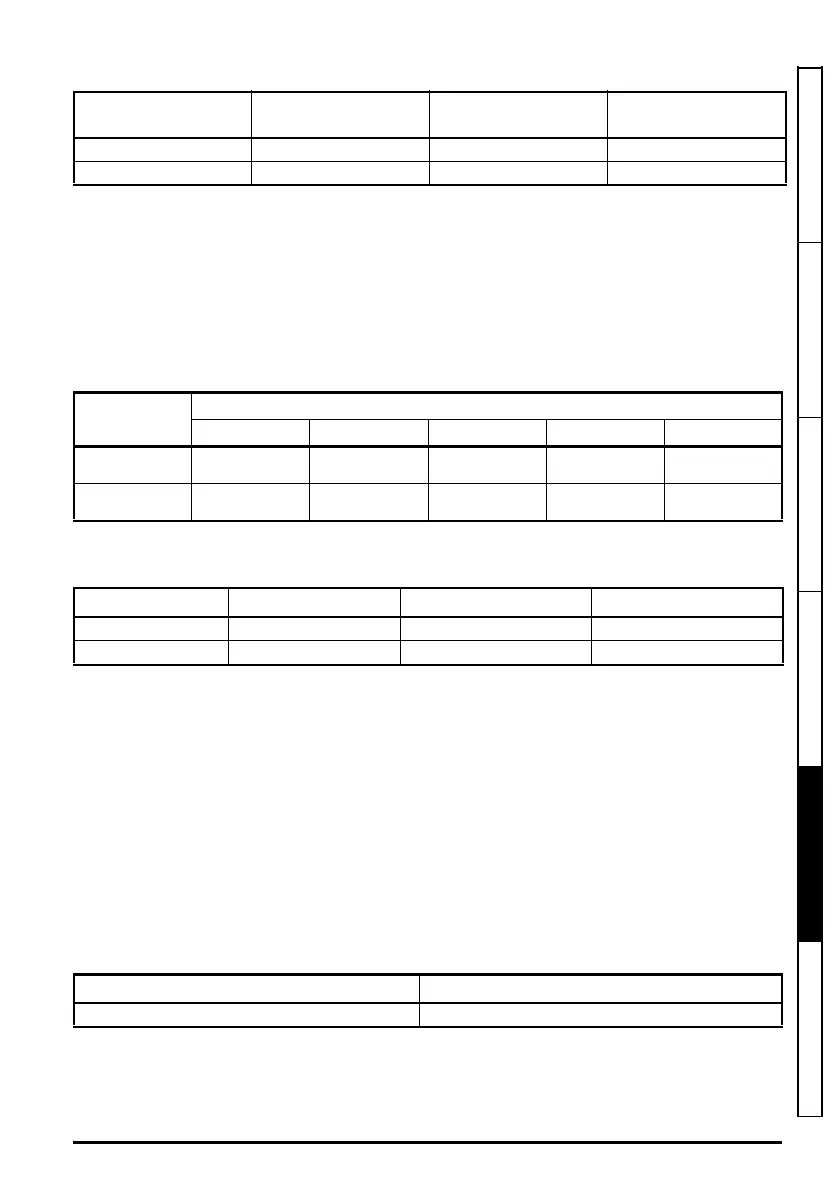
Table 5-14 Acoustic noise data
*At 40 °C ambient and 3 kHz switching frequency.
5.1.19 Overall dimensions
H Height including surface mounting brackets
W Width
D Projection forward of panel when surface mounted
F Projection forward of panel when through-panel mounted
R Projection rear of panel when through-panel mounted
Table 5-15 Overall drive dimensions
5.1.20 Weights
Table 5-16 Overall drive weights
5.1.21 Input current, fuse and cable size ratings
The input current is affected by the supply voltage and impedance.
Typical input current
The values of typical input current are given to aid calculations for power flow and power loss. The
values of typical input current are stated for a balanced supply.
Maximum continuous input current
The values of maximum continuous input current are given to aid the selection of cables and fuses.
These values are stated for the worst case condition with the unusual combination of stiff supply with
bad balance. The value stated for the maximum continuous input current would only be seen in one
of the input phases. The current in the other two phases would be significantly lower.
The values of maximum input current are stated for a supply with a 2 % negative phase-sequence
imbalance and rated at the maximum supply fault current given in Table 5-17.
Table 5-17 Supply fault current used to calculate maximum input currents
Size
Max ND operation
dBA
Max HD operation*
dBA
Min fan speed
dBA
5 61.1 56.9 41.9
6 65.3 55.6 48.2
Size
Dimension
HWD F R
5
391 mm
(15.39 in)
143 mm
(5.63 in)
200 mm
(7.87 in)
135 mm
(5.32 in)
67 mm
(2.64in)
6
391 mm
(15.39 in)
210 mm
(8.27 in)
227 mm
(8.94 in)
131 mm
(5.16 in)
96 mm
(3.78 in)
Size Model kg lb
5 All variants 7.4 16.30
6 All variants 14 30.90
Model Symmetrical fault level (kA)
All 100