Chapter 3 Operation of Each Part
11 Polarizer Turret
34
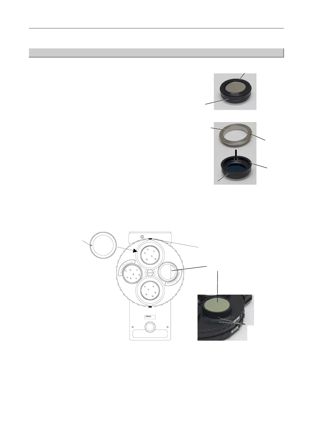
(2) Attaching the IR Polarizer
1
Separate the upper part (band pass filter and 1/4
lambda plate) and the lower part of the IR
polarizer.
2
Insert the adjustment tool for the 1/4 lambda plate
orientation, which is provided with the polarizer
turret, into the lower part of the IR polarizer.
In doing so, adjust the notch position on the
adjustment tool for the 1/4 lambda plate and the
protrusion position on the lower part of the IR
polarizer.
Rotate the knurled ring on the right side of the polarizer turret to adjust the index (a white
point) to the center line of the scale. Insert the IR polarizer assembled in Step 2 into the upper
turret of the polarizer turret. The notch of the IR polarizer must be oriented in the way as
shown in the figure.
3
JAPAN
FN-PT
4
Attach the polarizer turret into the microscope body.
5
Rotate the knurled ring on the right side of the polarizer turret and search the position where
the view becomes darkest. After the adjustment, tighten the clamp screw.
djustment
tool for the 1/4
lambda plate
orientation
Lower part of the IR polarizer
Notch
Lower part
Upper part
(Band pass filter and 1/4 lambda plate)
lign the white
point and the
center line.
Notch
Clamp screw
Protrusion
Knurled ring