11
Extension cable HMI control panel
Functional cable
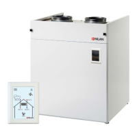
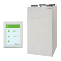
The control panel for the ventilation unit is connected up with a short wire so it can be installed close to the
unit.
If you place the unit so the control panel is out of sight, for instance in a cupboard or
in the loft, you can order a 15 m extension cable with plug. This allows you to place the control panel where it
is visible to the user.
It is important that the control panel is visible so the user can see alarms when, for example, filters need
replacing.
The following external functions can be connected to the ventilation unit via an RJ45 connector:
• User selection 1 and 2 (cooker hood)
• Modbus communication
• Fire thermostat or external fire automation system
You can adapt an RJ45 connector yourself in line with the instructions. To facilitate installation, Nilan can
supply a 10 m LAN cable with the correct RJ45 connector for the three functions.
 Loading...