30
CO
2
sensor
If the extent to which a dwelling/building is used varies considerably, you will benefit from installing a CO
2
-sensor to control the air
exchange. The CO
2
-sensor measures the CO
2
-level in the extract air. It then regulates the fan speed level accordingly.
Installation of CO
2
-sensor:
Connect the power supply 230V to the circuit board.
ATTENTION
In order to be able to connect up a CO
2
-sensor, the ventilation unit must have an expansion PCB. This must be purchased
separately, but if you have ordered an after-heating element, an expansion PCB is included.
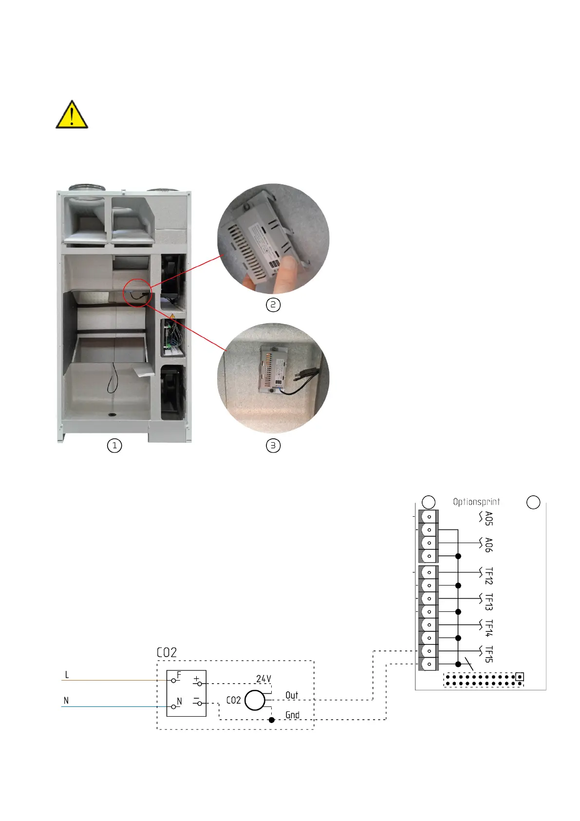
1. Detach the front door of the ventilation unit.
Remove the temperature sensor T4 from the
counterflow heat exchanger. Then lift the
counterflow heat exchanger out of the unit.
Install the CO
2
-sensor on the sloping surface
behind the counterflow heat exchanger.
2. Mount the CO
2
-sensor on the attached bracket
with hooks. Then press the CO
2
-sensor firmly
into place in the EPS.
3. Feed the wires from the CO
2
-sensor through
the hole where also the humidity-sensor and
the T3 outdoor temperature-sensor run
through. Then connect them to the expansion
PCB of the control system as shown below.
 Loading...