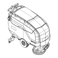
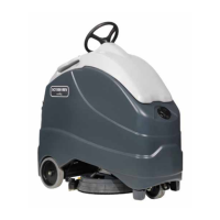
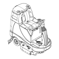
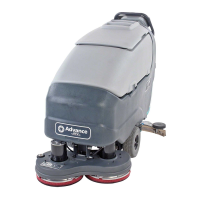
Service Manual: SC750, SC800, SC 750 ST, SC800 ST
Form Number 56043150 Page 100
Check the middle posion switch.
• Put the black ohmmeter lead on the Brown wire at the J2 connector pin 2.
• Put the red ohmmeter lead on the Yellow wire at the J2 connector pin 11.
• Drive the actuator motor all the way up and down using jumper wires powered by bat-
tery posive and negave. Connect them to the two actuator motor wires at the Main
Machine Controller connector. (Pink wire at connector J1 pin 4 and Gray wire at connec-
tor J1 pin 5.) Change polarity to change direcon. Immediately remove jumper wires at
the end of motor travel.
• Monitor the ohmmeter. It should show an open circuit (no connuity) only when the
actuator is in the middle posion. In all other posions it should show a closed circuit
(connuity).
Check the extended posion switch.
• Put the black ohmmeter lead on the Brown wire at the J2 connector pin 2.
• Put the red ohmmeter lead on the Green wire at the J2 connector pin 12.
• Drive the actuator motor all the way up and down using jumper wires powered by bat-
tery posive and negave. Connect them to the two actuator motor wires at the Main
Machine Controller connector. (Pink wire at connector J1 pin 4 and Gray wire at connec-
tor J1 pin 5.) Change polarity to change direcon. Immediately remove jumper wires at
the end of motor travel.
• Monitor the ohmmeter. It should show an open circuit (no connuity) only when the
actuator is in the extended posion. In all other posions it should show a closed circuit
(connuity).
• Wiring
• Main Machine Controller

 Loading...

