70 - FORM NO. 56043093 / Captor
™
4300, 4800, 5400
HYDRUALIC SYSTEM
FIGURE 4
TO TEST RELIEF VALVE SETTING PUMP CIRCUIT 2A
Insert hydraulic test gauge (3000psi) to the XT 2 test port.
To check, the hydraulic oil must be warm and engine in high speed (2400rpm).
Turn steering wheel to its stop and hold. The pressure reading should be 1850psi. Remove, clean and inspect. If still not correct
replace steering control unit.
SETTING RELIEF VALVE PUMP CIRCUIT 2B
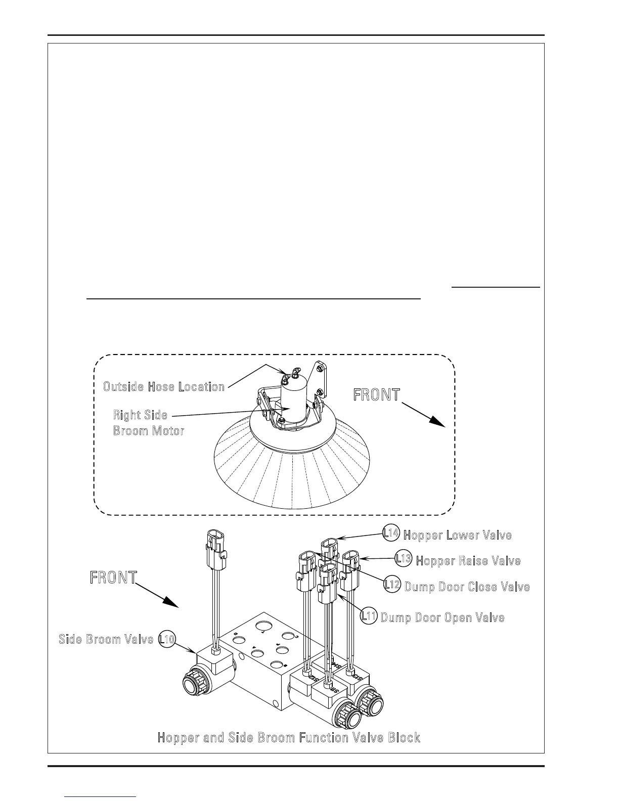
Open the hopper lter door and remove the lter and metal cover under the lter. Connect adapter cord PN 56407502 to L10 side
Broom solenoid coil, (wire colors ORG & BRN/BLK) and carefully lower the door back in place do not latch. Raise the hopper part way
and lower the side brooms. Cap the right side broom drive motor inlet hose # 37 (outside hose at motor). Finish raising the hopper
and engage the safety latch. Carefully reopen the door.
Open engine hopper door panel to access pump relief valve block assembly.
Insert hydraulic test gauge (3000psi) to the XT 2 test port.
To adjust, the hydraulic oil must be warm and engine in high speed (2400rpm).
Energize L10 side broom solenoid using the adapter cord. The pump circuit 2B will be in overload and the engine fan will stop
running use caution not to leave in overload for a long period. May cause engine damage.
Observe the pressure gauge and adjust accordingly. Relief should be at 2400psi. CCW to decrease pressure CW to increase.
FRONT
Dump Door Open Valve
L11
L12
Dump Door Close Valve
Side Broom Valve
L10
L13
Hopper Raise Valve
L14
Hopper Lower Valve
FRONT
Outside Hose Location
Right Side
Broom Mo tor
Hopper and Side Broom Function Valve Block