6
MACHINE DESCRIPTION
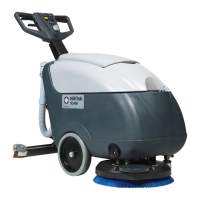
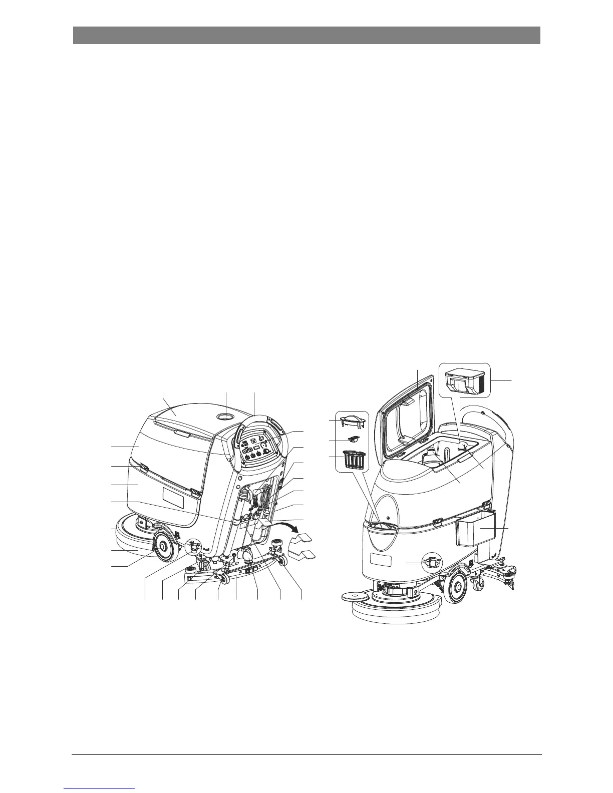
MACHINE STRUCTURE (as shown in Figure 1)
1. Recovery tank lid
2. Can holder
3. Handlebar
4. Control panel
5. Squeegee lifting/lowering lever
6. Garden coupling
7. Power supply cable holder
8. Power cable
9. Solution drain and level check hose
10. Deck lifting/lowering pedal
a) Pedal position when deck is lifted
b) Pedal position when deck is lowered
11. Squeegee knobs
12. Serial number plate/technical data
13. Squeegee vacuum hose
14. Squeegee
15. Squeegee balance adjusting knob
16. Solution/clean water tap
17. Rear steering wheels
18. Solution filter
19. Front wheels on fixed axle (A).
Driving wheels (B)
20. Brush/pad-holder
21. Brush/pad-holder deck
22. Recovery water drain hose
23. Solution tank
24. Hinge
25. Recovery tank
26. Filter support
27. Filler hose holder
28. Filter cover
29. N/A
30. Tank cover gasket
31. Debris collection box (*)
32. Bend tube
33. Float ball filter
34. Mop and trash kit (*)
35. Solenoid valve
(*): Optional
(A): Only for machine without traction
(B): Only for machine with traction
Figure 1
1 2
3
25
24
23
21
20
19
18
17 16 15 11 14 13 11
4
5
6
7
8
9
10
30
28
27
26
10b
10a
31
32
33
35
34
12
22
 Loading...