60 / 76 ♦ BKI16ATEX0018X ♦ htk4014a0600p_03
5.4 MICROTREK 2-WIRE T.D.R. METER CHARACTERISTICS
This subsection explains:
the four principle configurations for setting up a measurement scale and what the user should be aware of in each case;
what happens when the tank is full or empty;
what is the level threshold and how to modify it and
what happens when level is measured when more than one product in the tank;
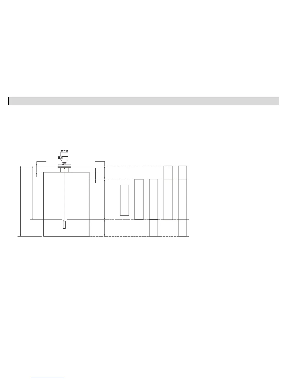
The measurement scale:
five possible configurations for analogue current output – with “Level” selected in PCSTAR 2 function 1.3.1 : Current 1 Item
A Tank height (Fct. 1.1.1)
B Probe length (Fct. 1.1.6)
C Detection delay (Fct. 1.5.1)
D Non-measurable zone
E Minimum distance between non-
measurable zone and dead zone
(Fct.: 1.1.2 – Fct.: 1.5.1)
F Upper dead zone (Fct. 1.1.2)
G Measuring range
Reference point at tank bottom
E
F
G
D
H
C
B
A
Display frozen in top dead zone
20mA 20mA
20mA20mA
20mA
4mA 4mA
(1) (2) (3) (4) (5)
Display frozen
below the probe
4mA
4mA 4mA
H
(Fct.: 1.3.1 = Level)