BKI16ATEX0018X ♦ htk4014a0600p_03 ♦ 25 / 76
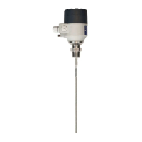
4.3 WIRING
Wiring in non-Ex environment
1 Detach the cover of the unit
2 Guide the cable into the housing through the cable gland
3 Remove a 4 mm length of isolation from the wires and
cut away the free part of the shielding.
4 Connect the wires of the current loop to terminals 2 and 3 (any polarity).
5 Pull back the cable till a 10 mm cable length remain in the housing behind
the cable gland.
Tighten the cable gland using two spanners.
Check the connection of wires and the tightness at the cable gland.
6 Array the wires in the housing and screw the cover on the housing.
The 500V AC insulation test should not be performed on the instrument
because of the overvoltage protection of the electronics.
123456
123456
HTK-402-4M-200-00
4…20 mA
I- I+
mV
Te s t
10 mV 1 mA
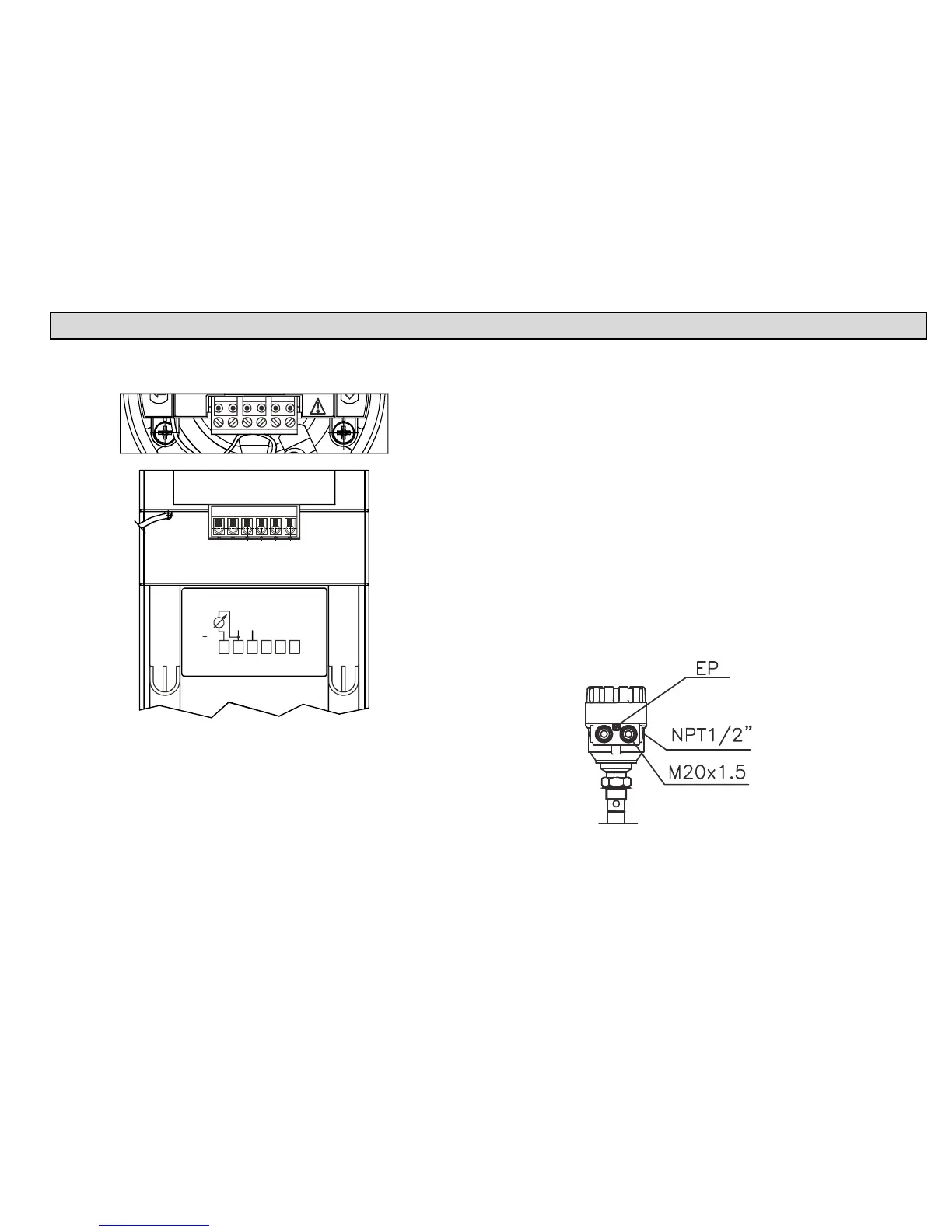
Connection to the EP network (grounding).
Screw type terminal (EP) on the housing max. cable cross-section:
4 mm².
The housing of the MicroTREK must be grounded.
Grounding resistance R < 1 Ohm
The shielding of the signal cable should be grounded at the control room.
Avoid coupling of electromagnetic noises place the singnal cable away
from power-current cables.