66 / 76 ♦ BKI16ATEX0018X ♦ htk4014a0600p_03
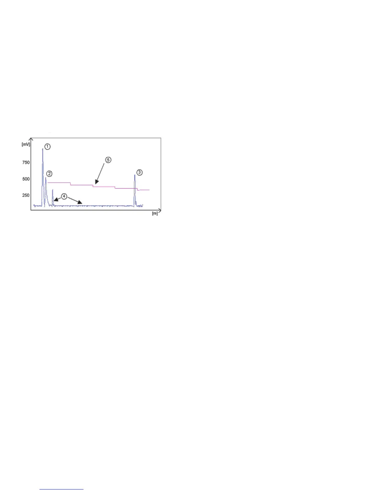
1 Initial pulse
2 Flange reflection
3 Level signal
4 Interference signal
5 Threshold
In the diagram above it can be seen that the level of the threshold is not constant:
400 mV at 1000 mm or 3.3 ft, and only 250 mV at 10000 mm or 33 ft. No attenuation is required at a probe length ≤ 3000 mm or 10 ft.
The form of the threshold is dependent on attenuation and is automatically adjusted by the device over the measured length.
Setting the level threshold
If the level threshold is set too high, i.e. it is greater than the amplitude of the level reflection,
the device will not find any level even with maximum amplification.
If the level threshold is set too low, i.e. it is below the amplitude of some of the interference signals,
the device will identify and indicate one of these interference signals as a level reflection only if the tank is empty.
Precise setting of the level threshold is especially important when the dielectric constant ε
r
is low.
To set, the level (amplitude of the reflection) must be known. A level of 500 mm or 20” is ideal.
The level threshold should be half-way between the invalid interference signals and the level reflection signal.
The reflection from the probe tip, which is clearly identifiable at a low ε
r
value, does not need to lie below the level threshold.
Take a look at all the reflections over the entire probe length and then change the level threshold and/or the amplification factor in the “Dynamic configuration (F11)”
menu.