52
3 Drive/brake system
3-1 Overview
3-1-1 Component
The drive/brake system includes the following:
1 The drive motor controlled by the controller transmits the rotational force to the drive shaft
(electricity mechanical power).
2 The drive shaft converts the rotational force transmitted from the drive motor into torque and
speed suitable for driving through its gear set, and sends them to the corresponding wheels
(mechanical power). They also include service brakes, which use a controller to control
electromagnetic brakes to generate braking power (friction).
3 The accelerator sends a CAN number to the drive motor controller to accelerate the motor (CAN
signal).
3-2 Drive assembly
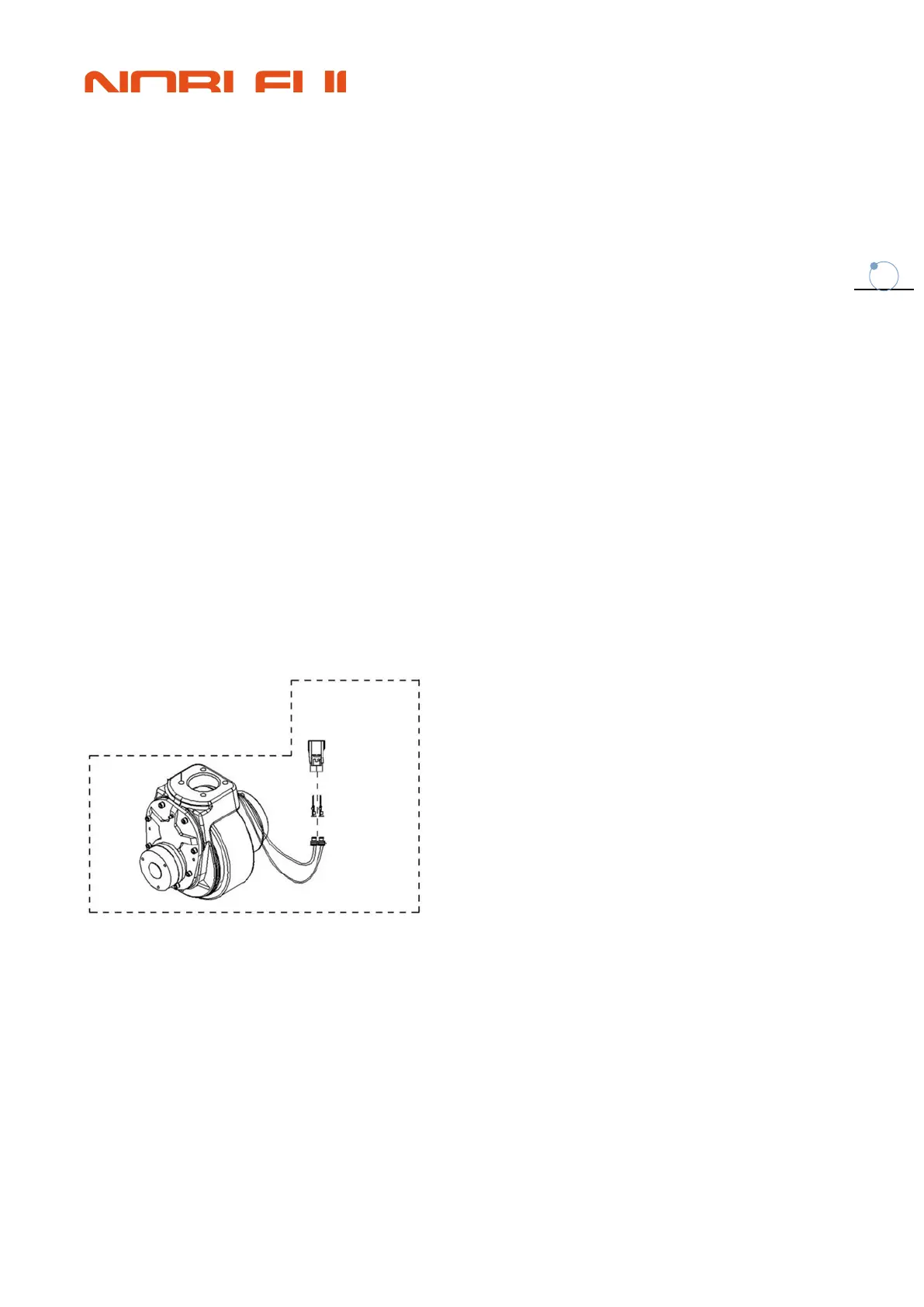
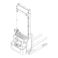
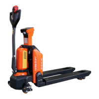
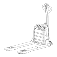
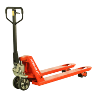
3-2-1 appearance
3-2-2 How does this work
On the electric side, the driving motors rotate their drive wheels so that the vehicle can move
forward/backward
Controlled by the controller
Each drive motor is connected to the controller via M1 and M2 lines. The controller runs the drive
motor based on input from multiple switches and sensors and internal parameter Settings。
When the following conditions are met, the drive motor operates:
1. Open the key and emergency stop switch to supply power to the controller.





 To Next Page