D
diazalexandraSep 12, 2025
What causes LOWER_DRIVER_FAULT in Noblelift PS E12B Trucks?
- QqhernandezSep 12, 2025
LOWER_DRIVER_FAULT in Noblelift Trucks is caused by Drive 2 (J1-11) failure.
What causes LOWER_DRIVER_FAULT in Noblelift PS E12B Trucks?
LOWER_DRIVER_FAULT in Noblelift Trucks is caused by Drive 2 (J1-11) failure.
What causes LIFT_DRIVER_FAULT in Noblelift Trucks?
LIFT_DRIVER_FAULT in Noblelift Trucks is caused by Drive 1 (J1-3) failure.
What does PDO_TIMEOUT mean in Noblelift PS E12B Trucks?
PDO_TIMEOUT in Noblelift Trucks is caused by handle communication timeout.
What does GAGE_PDO_TIMEOUT mean in Noblelift PS E12B Trucks?
GAGE_PDO_TIMEOUT in Noblelift Trucks is caused by instrument communication timeout.
What does MAIN_RELAY_DNC mean in Noblelift Trucks?
MAIN_RELAY_DNC in Noblelift Trucks occurs when the electronic control internal contactor is not closed.
What to do if HARDWARE_FAULT occurs in Noblelift PS E12B Trucks?
If you are experiencing HARDWARE_FAULT with your Noblelift Trucks, check the Controller.
What does MAIN_DRIVER_FAULT mean in Noblelift PS E12B?
MAIN_DRIVER_FAULT in Noblelift Trucks is caused by an internal main contactor problem.
What causes HPD_FAULT in Noblelift PS E12B?
The HPD_FAULT in Noblelift Trucks is caused by the wrong interlock, accelerator operation sequence; or after emergency reverse action, accelerator does not return to center.
What does Wiring Fault mean in Noblelift PS E12B?
A Wiring Fault in Noblelift Trucks is caused by an accelerator problem.
What causes a Throttle Fault in Noblelift PS E12B?
A Throttle Fault in Noblelift Trucks is caused by an accelerator wiring problem.
Explains the structure and purpose of the service manual.
Defines the warning labels used throughout the manual for safety.
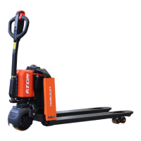
Introduces the components of the electronic system.
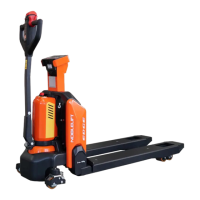
Details the appearance and specifications of the lithium battery.
Describes the appearance, specifications, and function of the emergency stop switch.
Covers the appearance and features of the controller and related components.
Discusses fuses and horns as miscellaneous loads in the system.
Details the appearance, function, and detection of the handle head.
Explains the operation, connection, and menu content of the handheld programmer.
Lists fault codes, their causes, and sources of failure.
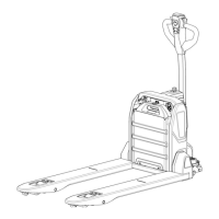
Provides a general overview of the drive/brake system components.
Explains the appearance and working principle of the drive assembly.
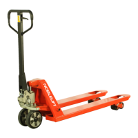
Describes the components and operation of the service braking system.
Offers solutions for drive motor and driving box issues.
Introduces the components and operation of the hydraulic system.
Details the appearance, specifications, and testing of the pump station.
Explains the appearance and replacement of hydraulic fluid and filters.
Provides troubleshooting for pump motor and hydraulic pump issues.
Introduces the components of the lifting system.
Details the appearance and operation of the door frame and its components.
Lists failure phenomena and possible reasons for lifting system issues.
Explains the structure and working principle of the steering system.
Presents the hydraulic schematic diagram with component identification.
Displays the electrical schematic diagram with component labeling.
Introduces the lithium battery charger and its technical parameters.