NORAM 65ET GRADER
3-11
Operation
3
Moldboard and Implement Operation
MOLDBOARD AND IMPLEMENT OPERATION
The moldboard and optional implements are hydraulically operated. Control levers are located on
each side of the front console. By actuating a switch on top of the front console, some control levers
operate multiple functions.
The transmission gear and engine speed should be set before engaging the ground with the
moldboard or implement. Never overload moldboard to the point that the rear wheels begin to slip.
This will alter the grade, increase wear on the tires and cause inefficient operation.
NOTICE: Using moldboard to back drag material should be avoided, if possible. Increased wear on the
moldboard guides and damage to the side shift cylinder rod may result.
Implement
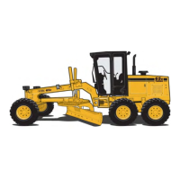
NOTICE: Front and rear-mounted implements, if installed,
have lock pins
(1) that must be removed to lower
implement.
The front of the motor grader may be equipped with an
optional dozer or scarifier. The rear of the motor grader
may be equipped with an optional ripper. They are
hydraulically operated. The scarifier and ripper can be
used to break out hard-packed material that the
moldboard can not penetrate. The dozer blade may be
used to level large piles which are not suitable to drive
the front wheels over.
NOTE: Front counterweights or front implements must be installed when rear ripper is
installed. Rear ripper and rear counterweights cannot be installed simultaneously.
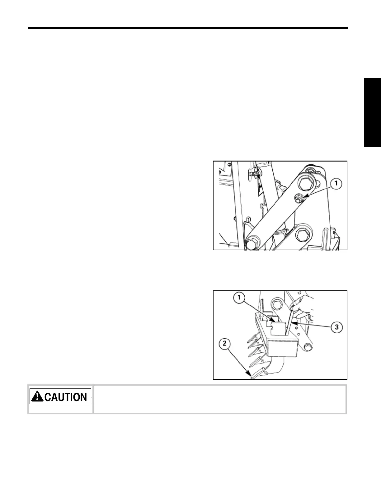
Scarifier and ripper shanks have two depth positions.
Each shank
(1) is equipped with a replaceable tooth, 2.
A lock pin
(3) holds the shank in place. To remove lock pin, tap on the bottom with a hammer until
free. Remove lock pin from the top of the tool bar and remove or reposition the shank.
To install, position shank in tool bar in the desired notch. Insert lock pin from top of tool bar until
fully seated.
Keep feet out from under toolbar, shanks may fall when lock pin is removed.