www.norcold.com/cda
16
Refrigerator Service ManualN611v, N811v Models
Fault Codes - cont’d.
Continuous 12-Volts:
See Fig. 6 on page 17.
12VDC is supplied to the refrigerator at Power Board terminals
12VDC & GND [A]. This 12VDC travels through the Power
Board to fuse F1 [B] and then out to P1-6 [C]. Via the green
wire, the 12VDC exits the Power Board and enters the Display
Board at P1-1 [D]. The 12VDC travels through the Display
Board to one side of the normally open On-Off switch [E]. This
12VDC is referred to as the continuous 12-volts because it
is always present at the one side of the On-Off switch when
12VDC power is applied to the refrigerator.
Blank Display
Switched 12-Volts:
See Fig. 7 on page 17.
Pressing the On-Off switch [E] will allow 12VDC to pass
through the On-Off switch and back to the Power Board via
the blue wire [F] connected between the Display Board at P1-3
and the Power Board at P2-3. Once the 12VDC reaches the
Power Board, a signal is sent out to the coil of relay K3 [G]
via the U1 microprocessor. This signal allows the K3 relay to
energize thus closing the normally open contacts [H].
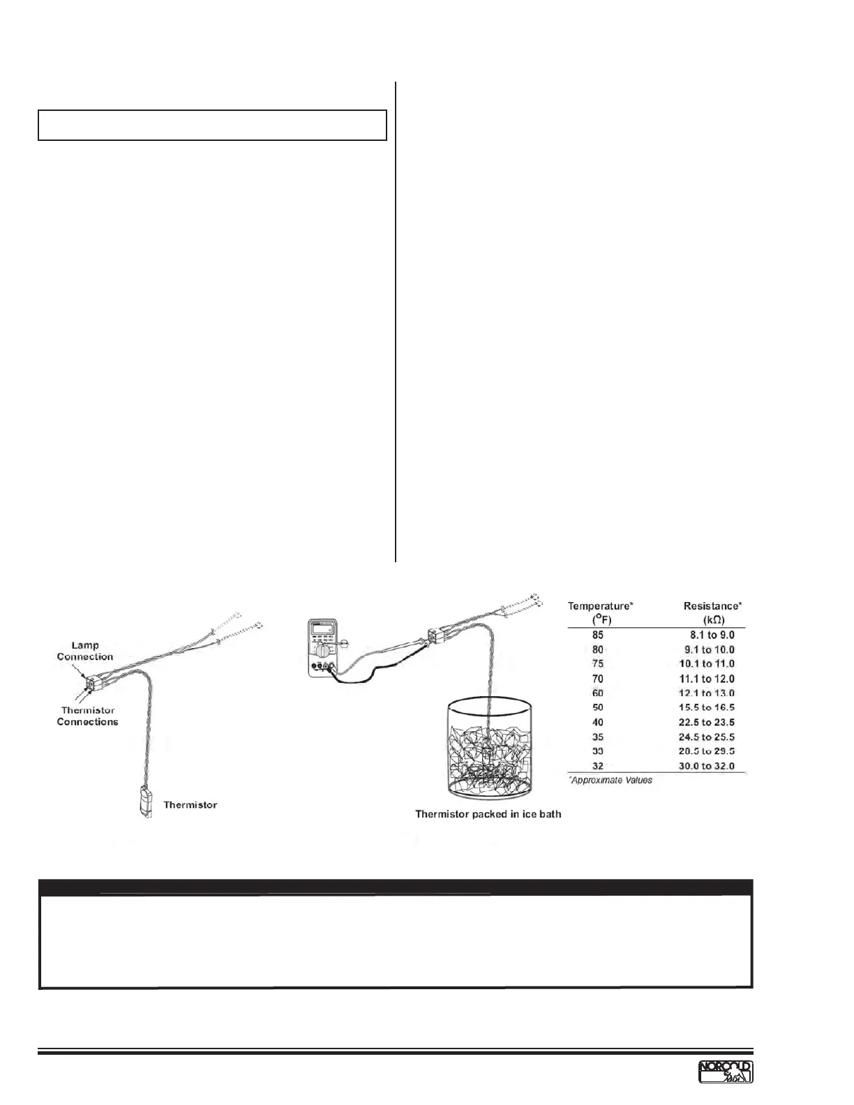
Fig. 5A - Thermistor
Fig. 5B - Thermistor in Ice
K3 is a latching relay. Once the relay coil is energized the contacts close and remain closed even when the 12VDC is re-
moved, hence the term “latching relay”. With the K3 contacts now closed, 12VDC is passed back to the Display Board via the
White-Red wire [J] between P1-9 of the Power Board and P1-2 of the Display Board. This 12VDC will remain at P1-2 until the
latching relay is “un-latched”, which will not take place until the On-Off button is depressed again. This 12VDC is termed the
switched 12-volts and is used to power ON the display.
NOTE
On-Off Theory of Operation:
 Loading...