www.norcold.com/cda
25
N611v, N811v ModelsRefrigerator Service Manual
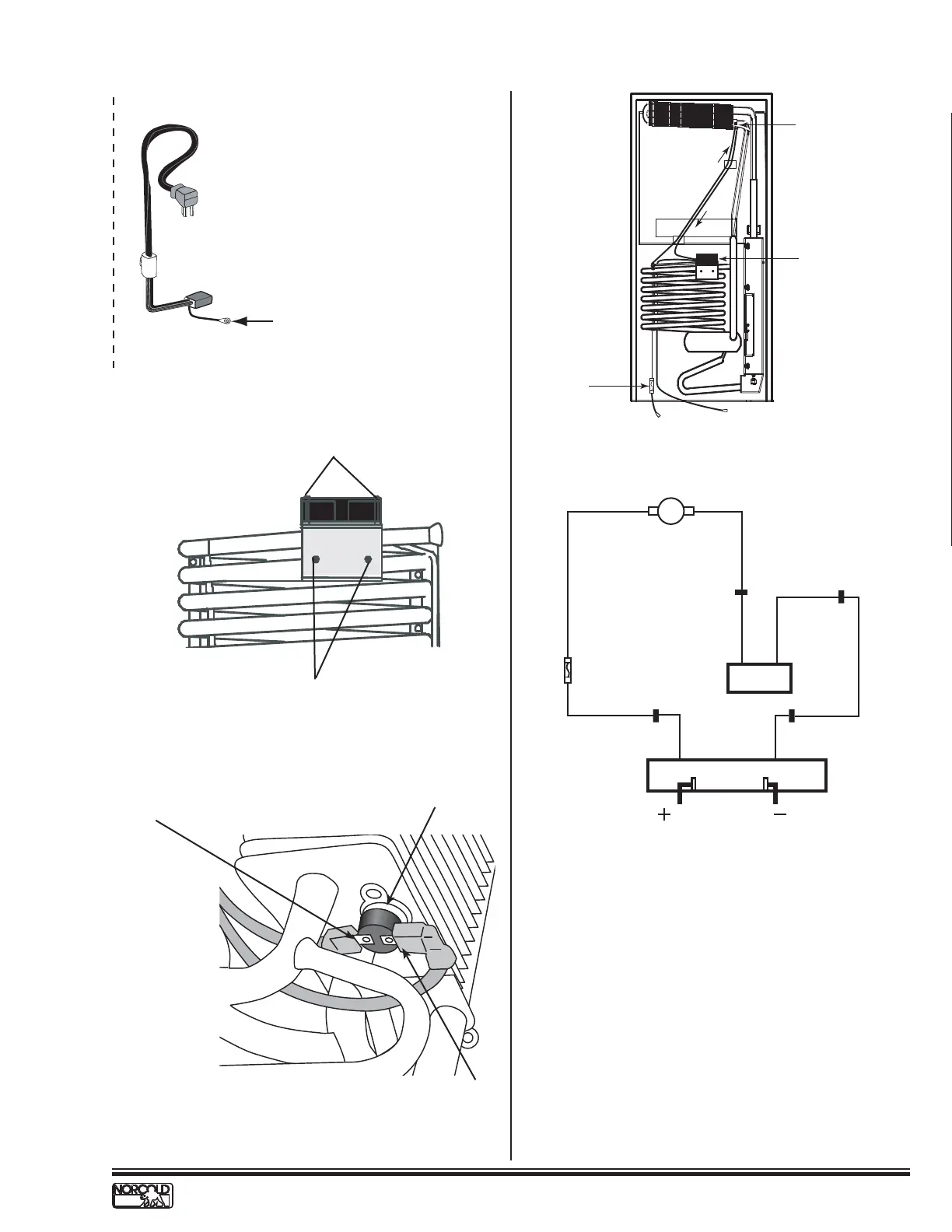
Fig. 19 - Fan Mounted on Top of Absorber Coil.
Fig. 20 - Fan Thermostat.
Fig. 18 - AC Power Cord.
Ground wire
REFRIGERATORS WITHOUT ICE MAKERS
(a)
Outer bracket and mounting screws
Fan mounting screws
Electrical Requirements and Components - cont’d.
NOR000098A
NOR000095A
+ 12VDC input to
thermostatic switch
Fan thermostatic
switch
+12VDC wire to fan
connection
Fig. 22 - NORCOLD Fan Kit Wiring Pictorial.
Fig. 21 - Fan with Installed NORCOLD Fan Kit.
Fan
thermostatic
switch
Fan
+ 12 Vdc connection
- 12 Vdc connection
1 amp
in-line fuse
Red wire
to thermal
switch
Red wire to fan
POWER BOARD
Red Spliced Wire
1AMP
FUSE
Red
Fan
Wire
Red
Wire
THERMOSTAT
12 VDC
GND1
Black Spliced Wire
Black
Wire
Black
Fan
Wire
Red
Wire
FAN
12 Vdc12 Vdc
 Loading...