www.norcold.com/cda
2
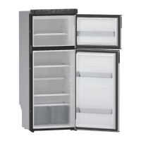
Refrigerator Service ManualN611v, N811v Models
CONTENTS
Introduction .................................................................................................. 3
About this Manual ................................................................................... 3
Model Identification ................................................................................. 3
Information Label .................................................................................... 3
Certification and Code Requirements ..................................................... 3
About Installation .................................................................................... 3
Replacement Parts ................................................................................. 3
Technical Assistance ............................................................................... 3
Model Identifi cation .....................................................................................4
Cooling Unit Serial Number .................................................................... 4
Safety Awareness ........................................................................................ 5
Safety Notice ...........................................................................................5
Attention Statements ...............................................................................5
Safety Statements ...................................................................................5
Specifi cations .............................................................................................. 6
Theory of Operation .................................................................................... 7
Overview ................................................................................................. 7
Cooling Unit ............................................................................................ 7
Leveled Operation ...................................................................................7
Gradual Decrease in Cooling Efficiency ................................................. 7
Gas Absorption System .......................................................................... 8
Electronic Controls .................................................................................. 9
Theory of Operation - Auto Modes ........................................................ 9
Background Operations ........................................................................ 10
Fault Codes ............................................................................................... 12
Diagnostic Prechecks ........................................................................... 13
Fault Code Flash Patterns .................................................................... 13
Solid Red Indicator Light ................................................................13
Fault / Flash Pattern 2 Service Error .............................................. 14
Fault / Flash Pattern 3 Open High Limit .........................................14
Fault / Flash Pattern 4 AC Relay Error ........................................... 14
Fault / Flash Pattern 5 Flame On, Should Not Be On ....................14
Fault / Flash Pattern 8 LOW DC (1) Error ......................................15
Fault / Flash Pattern 9 LOW DC (2) Error ......................................15
Thermister Fault .............................................................................15
Door Fault ....................................................................................... 15
Blank Display .................................................................................. 16
LP Gas System ......................................................................................... 18
Pressure Requirements ........................................................................ 18
Testing for LP Gas Leaks ...................................................................... 18
Components .......................................................................................... 19
Flame Appearance ................................................................................ 20
Burner Cleaning Procedure .................................................................. 21
Gas Lockout .......................................................................................... 23
Reset a Gas Lockout Condition - All Models .........................................23
Gas Safety Valve Test ........................................................................... 23
Electrical Requirements and Components ................................................ 24
DC Voltage Requirements and Polarity ................................................ 24
DC Power Wiring Requirements ........................................................... 24
AC/DC Converter as Power Source ...................................................... 24
12VDC Ventilation Fan ..........................................................................24
Cooling Unit ............................................................................................... 26
Cooling System Monitoring ................................................................... 26
Troubleshooting Cooling Faults ............................................................ 26
Refrigerant Leakage ............................................................................. 26
Disposal of Cooling Unit ........................................................................ 26
Cooling System Diagnostic Flowchart .................................................. 27
Wiring Pictorial ..................................................................................... 29
Modes Of Operation .................................................................................. 30
Refrigerator Start-Up ............................................................................. 30
Refrigerator Shut-Down ........................................................................ 30
Effects of High Altitude on Propane Gas Operation ..............................30
Effects of Freezing Temperatures on Refrigerator Operation ............... 30
Figures
Fig. 1 - Refrigerator Information Label Location .............................. 4
Fig. 2 - Cooling Unit Bar Code Label Location. ................................ 4
Fig. 3 - Gas Absorption System ........................................................ 8
Fig. 4 - Flash Patterns .................................................................... 13
Fig. 5A - Thermistor ....................................................................... 16
Fig. 5B - Thermistor in Ice .............................................................. 16
Fig. 6 - Continuous 12-Volt ............................................................ 17
Fig. 7 - Switch 12-Volt .................................................................... 17
Fig. 8 - LP Gas System Components. ............................................ 18
Fig. 9 - Solenoid Gas Valve. ........................................................... 19
Fig. 10 - LP15 Orifice Assemblies .................................................. 19
Fig. 11 - Burner ............................................................................... 19
Fig. 12 - Burner Tube ...................................................................... 19
Fig. 13 - Flue and Components ...................................................... 20
Fig. 14 - Flue Baffle ........................................................................ 20
Fig. 15 - Flame Appearance ........................................................... 20
Fig. 16 - Drip Cup and Burner Box Cover ....................................... 22
Fig. 17 - Burner and Components ................................................. 22
Fig. 18 - AC Power Cord. ................................................................ 25
Fig. 19 - Fan Mounted on Top of Absorber Coil. ............................. 25
Fig. 20 - Fan Thermostat. ............................................................... 25
Fig. 21 - Fan with Installed NORCOLD Fan Kit. ............................. 25
Fig. 22 - NORCOLD Fan Kit Wiring Pictorial. ................................ 25
Fig. 23 - Reset Pushbutton ............................................................. 26
Fig. 24 - Cooling System Diagnostics ............................................. 27
Fig. 25 - Wiring .............................................................................. 29
Fig. 26 - Wiring .............................................................................. 29
 Loading...