4 Commissioning
BU 0200 en-3118 127
Pos: 26 3.30 / Anlei tung en/ Ele ktr oni k/FU un d St art er/ 4. I nbetr ie bna hm e/AS-I nter face [all e Ger äte]/ Konfig urati on_02 (BUs I/O Bits_Ü bersc hrift ) @ 19\mod_1511865687254_388.docx @ 2373837 @ 5 @ 1
Bus I/O bits
Pos: 263. 31 / Anl eit unge n/ Elek tro nik/F U u nd St arter/ 1. Allg em ein es/ Sic herhei ts- und I nst alla tio nshi nw eise un d War n- G efa hre nhin weis e/n eu/W arn- und G ef ahre nhi nweis e/ WAR NUN G - U nerwar tete B ewegu ng durc h auto matis chen Anl auf (BU S-IO Kommunikation) @ 19\mod_1511866621376_388.docx @ 2373874 @ @ 1
WARNING
Unexpected movement due to automatic starting
In the event of a fault (communication interrupted or bus cable disconnection, the device automatically switches
off, since the device enable is no longer present.
Restoration of communication may result in an automatic start and therefore, unexpected movement of the drive
unit. To prevent any hazard, a possible automatic start must be prevented as follows:
• If a communication error occurs, the bus master must actively set the control bits to "zero".
Pos: 263. 32 / Anl eit unge n/ Elek tro nik/F U u nd St arter/ 4. Inb etri eb nah me/A S-I nter face [all e Ger äte]/ Ko nfig urat ion _03 (BU s I/ O Bi ts) [S K 1 x0E, SK 2xx E] @ 9\mod_1444290892980_388.docx @ 248908 @ @ 1
Initiators can be directly connected to the digital inputs of the frequency inverter. Actuators can be
connected via the available digital outputs of the device. The following connections are each provided
for four reference data bits:
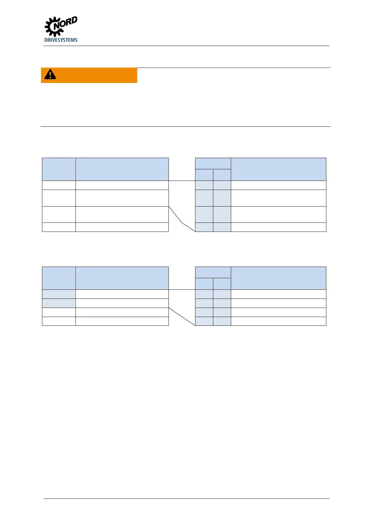
BUS IN Function (P480[-01…-04])
Status
Status
Bit 1 Bit 0
Right rotation field is present at the
motor
Bit 2 Fixed frequency 2 ( P465[-02]) 1 0 Left rotation field is present at the
motor
Acknowledge with flank 0 1.
For control via the bus, acknowledgement is not
automatically performed by a flank at one of the enable
inputs
BUS OUT Function (P481 [-01 … -04])
Status
Status
Bit 1 Bit 0
Bit 2
Digital-In 1 status 1 0 Start disabled
1) Bits 2 and 3 are directly coupled to digital inputs 1 and 2
Pos: 263. 33 / Anl eit unge n/ Elek tro nik/F U u nd St arter/ 4. Inbetriebnahme/AS-Inter fac e [al le Ger äte] /Ko nfig ur ati on_ 04 (BU s I/O Bi ts ) [ SK 2 xxE] @ 1 1\mod_1458571942532_388.docx @ 314580 @ @ 1
The configuration of the I/O bits can also take place within a limited scope via DIP-switch S1: 3, 4 and
5 ( Section 4.3.2.2 "DIP switches (S1)").
Pos: 263. 34 / Anl eit unge n/ Elek tro nik/F U u nd St arter/ 4. Inbetriebnahme/AS-Inter face [all e Ger äte]/ Ko nfig urat ion _05 (BU s I /O Bi ts) [S K 1 xxE, SK 1x xE-FDS (, SK 1x0E , 2xxE - e ntfer ne n? --> pr üf en)] @ 9\ mod_1444295258020_388.docx @ 248940 @ @ 1
Parallel actuation via the BUS and the digital inputs is possible. The relevant inputs are dealt with
more or less as normal digital inputs. If a changeover between manual and automatic is going to take
place, it must be ensured that no enable via the normal digital inputs takes place in automatic mode.
This could be implemented e.g. with a three-position key switch. Position 1: "Manual left" Position 2:
"Automatic" Position 3: "Manual right".
If an enable is present via one of the two "normal" digital inputs, the control bits from the bus system
are ignored. An exception is the control bit "Acknowledge fault". This function is always possible in
parallel, regardless of the control hierarchy. The bus master can therefore only take over control if no
actuation via a digital input takes place. If "Enable left" and "Enable right" are set simultaneously, the
enable is removed and the motor stops without a deceleration ramp (block voltage).
Pos: 263. 35 / All ge mei n/Al lgem ei ngült ige M o dul e/---------Seitenumbruch kompakt --------- @ 13\mod_1476369695906_0.docx @ 2265495 @ @ 1
 Loading...


