NORDAC SK 200E Handbuch
158 Subject to technical alterations BU 0200 GB
7 Technical data
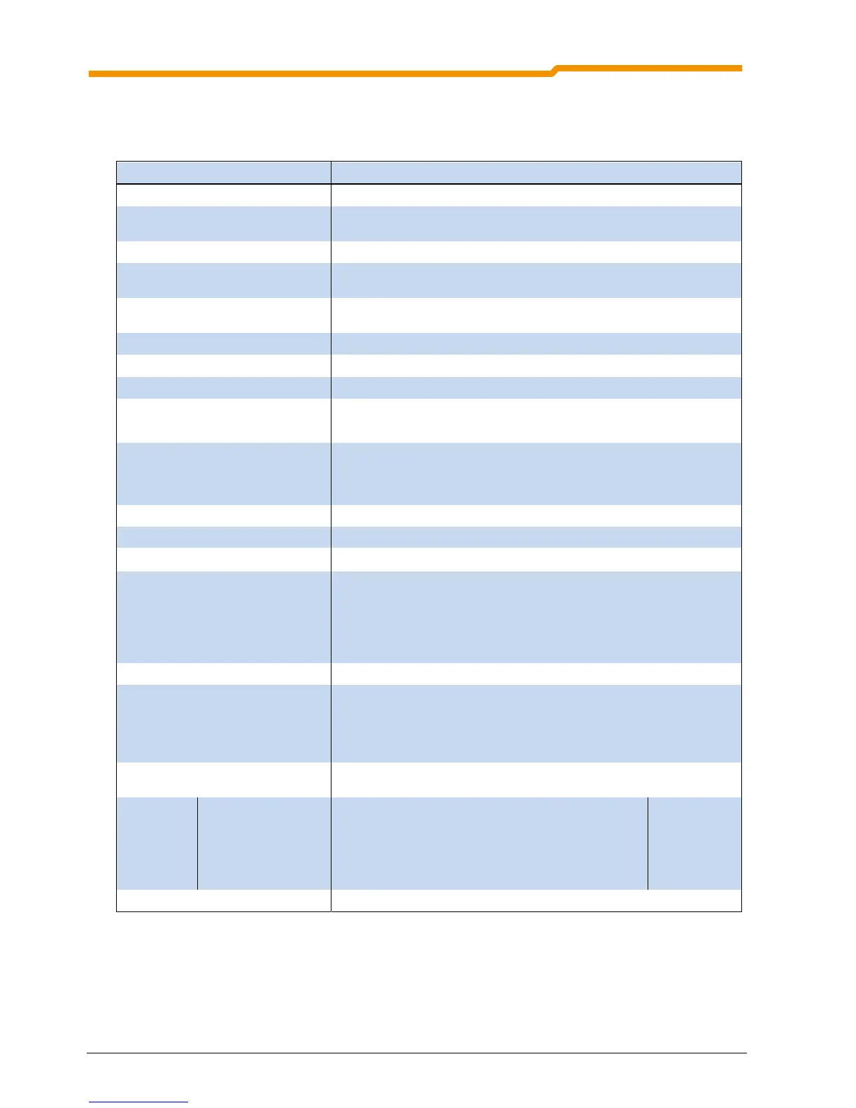
7.1 General Data SK 200E
Function Specification
Output frequency 0.0 ... 400.0Hz
Pulse frequency 3.0 ... 16.0kHz, standard setting = 6kHz
Power reduction > 8kHz for 115/230V device, >6kHz for 400V device.
Typical overload capacity 150% for 60s, 200% for 3.5s
Protective measures against Over-heating of the frequency inverter,
overvoltage and undervoltage
Short-circuit, earthing fault,
overload, idling
Regulation and control Sensorless current vector control (ISD), linear V/f characteristic curve,
automatic flux adaptation (energy-saving function)
Motor temperature monitoring I
2
t motor, PTC / Bimetal switch
Digital input
4x, low 0-5V, high 14-30V, R
i
= 9.5k, C
i
= 10nF, cycle time = 4ms
Electrical isolation Control terminals
Control outputs digital output:
Brake rectifier:
18-30V DC ( according to VI 24V), max. 200mA, max. 100k
load
max. 0.5A choke voltage, voltage according to mains
Interfaces Standard: RS 485 (USS)
RS 232 (Single Slave)
System bus
Option: Profibus
CANopen
DeviceNet
AS Interface
Efficiency of frequency inverter approx. 95% according to size
Ambient temperature Details in the following sections
Storage and transport temperature
-25
℃ ... +60 / 70℃
Long-term storage Connect the FI and the 24V modules to the mains voltage for 60 minutes at
the latest after one year.
Connect the FI and all other modules to be supplied with 24V to the 24V
control voltage for 60 minutes at the latest after one year.
Maintain this cycle throughout the storage period.
Protection class IP55, optional IP66
Max. mounting altitude above sea
level
Up to 1000m: No power reduction
1000...4000m: 1%/ 100m power reduction (up to 2000m overvoltage cat. 3)
2000...4000m: Only overvoltage category 2 is maintained, external
overvoltage protection at the mains input is necessary
Waiting period between two power-up
cycles
60 sec for all devices in normal operating cycle
Connection
terminals
Mains/motor/brake
resistance
4mm
2
flexible with wiring sleeves, 6mm
2
with rigid cable
Terminal screw
tightening
torque
1.2..0.10.5Nm
Control unit /System
bus
2.5mm
2
, with1.5mm
2
wiring sleeves
RS485 / RS232 1x RJ12 (6-pin)
External 24V supply voltage 18…30V DC, at least 200...800mA according to load

 Loading...
