Installation
A1-21
E 2000 Nordson Corporation
All rights reserved
41-3000V
Issued 5/00
A3EN-04-[3V-A-AAXP]-12
WARNING: Risk of equipment damage, personal injury, or
death. For a proper and safe installation, make sure you meet
the requirements in the following step.
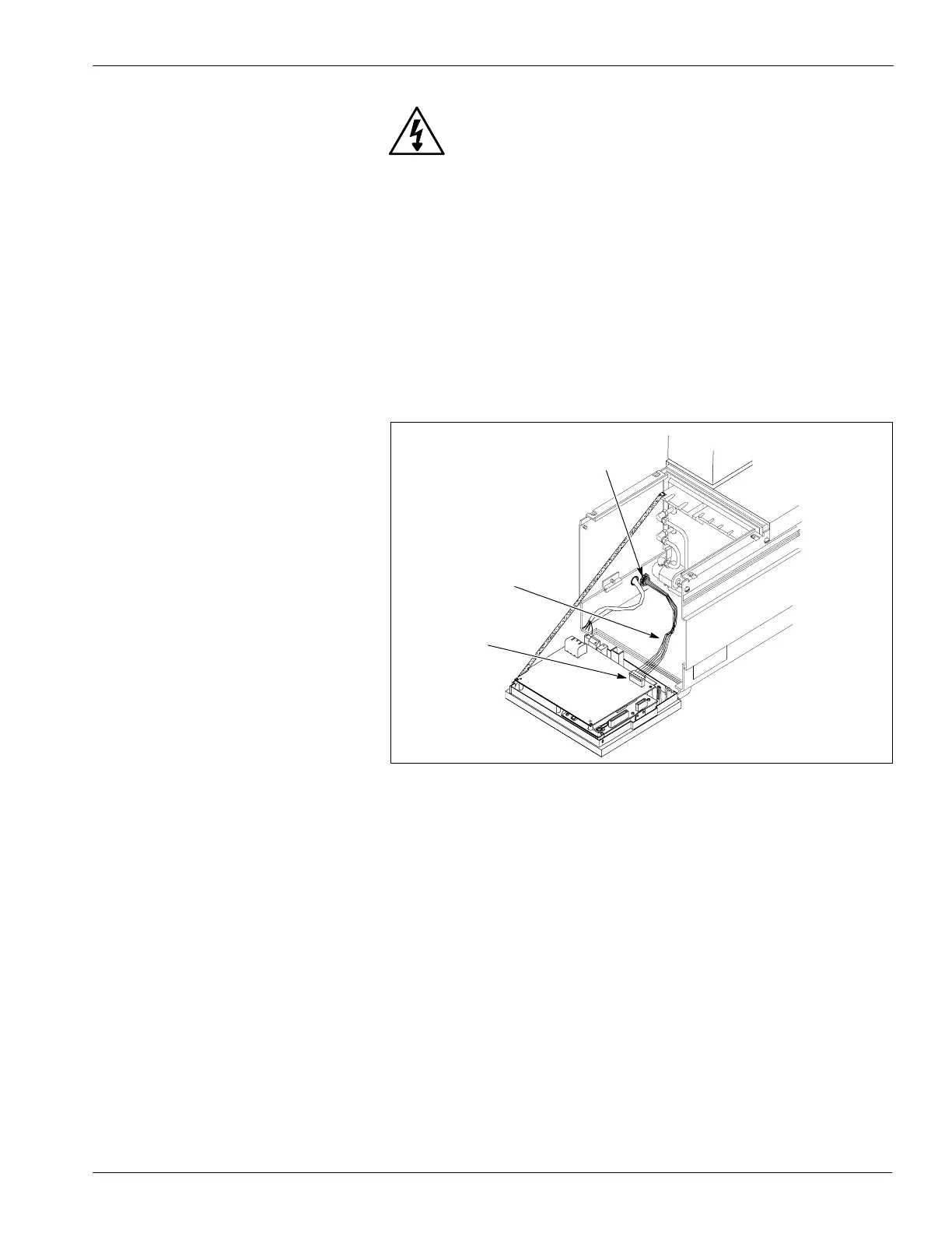
6. See Figure A 1-13. Route the output contact wires (2) through the
strain relief (1) to terminal block TB2 (3). Make sure your installation
meets these requirements:
S Use 0.34--0.25 mm
2
(22--24 AWG) stranded wire that is suitable
for National Electrical Code (NEC) Class 1 remote control and
signaling circuits. Output contacts are rated for 250 VAC, 2 A
maximum.
S Use the proper length of wire and route the wires so they do not
touch any of the printed circuit boards. Make sure the wires reach
terminal block TB2 when the electrical enclosure is opened.
4130923A
1
2
3
Fig. A 1 -13 Connecting Output Contacts
1. Strain relief
2. Output contact wires
3. TB2 terminal block
 Loading...


