© 2021 Nordson Corporation
7446567-02
10-5
Disassembly and Assembly
Valve Cartridge Disassembly
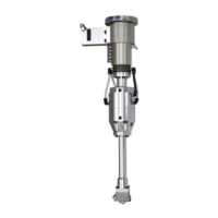
See Figure 10-2.
Refer to Figure 10-1.
1. Refer to Figure 10-1. Remove socket head cap screws securing the valve manifold
assembly to the smart gun base.
2. Refer to Figure 10-1. Remove the valve manifold assembly from the smart gun
base.
3. Refer to Figure 10-1. Remove the two ow tubes and valve cartridge assemblies
from the valve manifold assembly. At this time, all the ush plugs can be removed
as well, if necessary. The ow tube (and valve cartridge assemblies may remain
connected to the smart gun base valve ports instead of the valve manifold
assembly.
CAUTION:
• The spring (30) and spacer ring (31) are not secured and may fall out of the smart
gun
• Inspect the spring and spacer ring for damage and wear once removed. Replace if
necessary.
4. See Figure 10-2. Remove the seal retainer (21) from the valve cartridge assembly.
5. See Figure 10-2. Remove the needle/piston assembly (28, 27) from the valve
cartridge assembly.
CAUTION:
• Pull the needle/piston assembly (28, 27) out of the cartridge body (26), piston (28)
end rst.
• Ensure the needle/piston assembly is removed as linear as possible to avoid
damage to the needle shaft. If there is damage to the needle shaft replace needle.
6. See Figure 10-2. Remove the piston O-ring (29) from the needle/piston assembly
(28, 27).
CAUTION: Inspect the piston (28) O-ring (29) and replace if necessary.
7. See Figure 10-2. Utilizing a small pick, or equivalent tool, remove the small
diameter O-ring (32) located in the valve cartridge body (26).
CAUTION: See Figure 10-2. Inspect the O-ring for damage and replace, if necessary.
8. See Figure 10-2. Remove the needle sealing seal (33) and bearing (25) from the
cartridge body (26).
NOTE: Removal can be performed by pushing a, dull, small diameter, item through
the air section of the cartridge body (26) and push out the bearing (25) and seal (33).
9. See Figure 10-2. Remove the large diameter O-ring (24) in the outside O-ring
groove of the cartridge body (26).
10. See Figure 10-2. Remove the small diameter O-ring (22) and parbak ring (23) from
the small diameter outside O-ring groove.
 Loading...
