Do you have a question about the Nordson TCB and is the answer not in the manual?
Explains symbols used for special information regarding efficient use, damage prevention, or injury prevention.
Details where to mount the enclosure for optimal observation and minimal vibration.
Instructions for connecting pneumatic sensor lines for pressure measurement.
Covers main switch, motor connection, and supply voltage details.
Details supply voltage connections and the RS-485 bus interface.
Explains motor protection terminals and optional isolation amplifier connections.
Covers fan starters, alarm relay, and remote inputs.
Explains outputs for lamps, analogue signals, and valve connections.
Details the configuration of programmable inputs and outputs.
Describes the operation of the control board for single fan systems.
Details the operation of the control board for multiple fan systems.
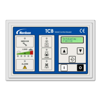
Explains the meaning of the status LEDs on the front display panel.
How to view system settings and current values on the LCD display.
Instructions on how to enter and use the setting mode for configuration.
Covers PIN code and accessing the setting mode.
Details parameters for Min/Max Delta P and alarms.
Covers off-line cleaning, star/triangle time, pulse intervals, and language.
Details configuration of programmable inputs and outputs.
Covers cleaning modes, valve configuration, time/date, and factory reset.
| Model | TCB |
|---|---|
| Manufacturer | Nordson |
| Type | Control Unit |
| Frequency | 50/60 Hz |
| Power Consumption | 300W |
| Heating Capacity | 300W |
| Interface | Digital Display, Keypad |
| Certifications | CE, UL |