Installation, Operation and Maintenance Manual
10
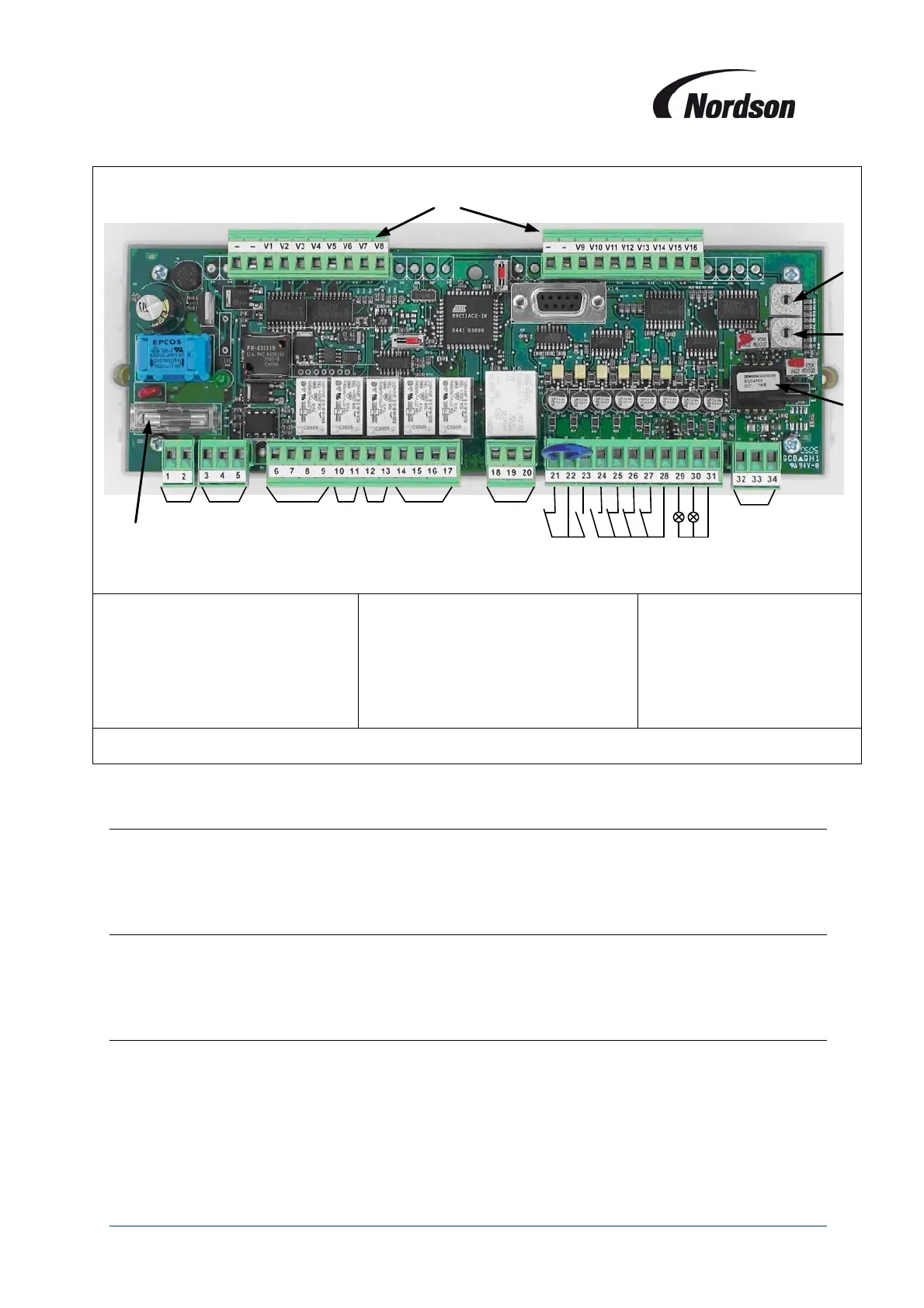
1. Pressure transducer
2. Cleaning mode switch
3. Module number switch
4. Valve connectors
(-, V1 – V16)
5. Input voltage 24 VAC (1,2)
6. RS 485 bus link
(3,4,5)
(Terminal Numbers)
7. Optional isolation amplifier
(6 - 9)
8. Output O1
(10,11)
9. Optional output O2 (12,13)
10. Fan starter
(14 – 17)
11. Alarm relay (18 – 20)
12. Remote ON/OFF terminals (21- 23)
13. External ON
(28, 24)
14. Fan alarm (28, 25)
15. Alarm input I1 (28, 26)
16. Alarm input I2
(28, 27)
17. ‘In use’ lamp (31, 29)
18. ‘Alarm’ lamp
(31, 30)
19. 4 – 20 mA
terminals (32 – 34)
Figure 2: Terminal view of I/O module PCB
3.3. Supply voltage: terminals 1 and 2
The supply voltage for the power box can be either 200V AC, 230V, 380V, 400V (standard TCB), 440V
or 480V, 50 or 60 Hz. A transformer with 63VA or 110VA output will be used. The electronic modules
will be supplied with pre-wired 24V AC on terminals 1 and 2.
3.4. RS-485 Bus: terminal 3–5
All TCB Circuit boards have an RS-485 interface for the communication between Display, I/O module
and slave valve modules. For multiple module systems the RS485 connection is pre-wired to socket
connections on the base of the main controller and the ends of the slave modules.
3.5. Motor protection: terminals 25, 28
An overload relay is used for the fan motor(s); the auxiliary contact will be connected to terminals 25
and 28 (multiple fan overloads will be connected in series). When the fan alarm triggers a shutdown of
the fan set, a re-start is only possible after shutting down the power to the control box and re-setting the
overload switch.
5 6 7 8 9 10 11 19
12 14 16 17 18
13 15
+24V DC
+24V DC
+24V DC
4
3
2
1
Fuse T 2A