Installation, Operation and Maintenance Manual
11
3.6. Optional isolation amplifier for thermistor protection and/or bursting disc: terminals 6–9
An optional isolation amplifier for motor thermistor protection or bursting disk observer circuit can be
plugged into the I/O module PCB. The input connections will be made to terminal 6 and 7; at terminal 8
and 9 a potential free contact (NC) is available as output signal. This output signal can then be used for
example to initiate an alarm in the TCB by connecting it to terminals 26 and 28.
The terminals for the thermistor will be included as standard on the TCB board, but the Thermistor
module itself is an option.
3.7. Connections for Fan starters : terminals 14–17 (+ 12 & 13 for ECB 4 units)
The contactors for fan starting will be connected as follows:
Terminal 14 = Common = 24V AC Supply.
Terminal 15 = Main contactor for Star-Delta systems, Fan 1 contactor for DOL / multiple fan systems.
Terminal 16 = Star contactor for Star-Delta systems, Fan 2 contactor for multiple fan system
Terminal 17 = Delta contactor for Star-Delta systems, Fan 3 contactor for multiple fan system.
For a 4 fan system :
Terminal 12 = Common = 24V AC Supply.
Terminal 13 = Fan 4 contactor.
These connections are made at the factory.
3.8. Alarm relay: terminals 18–20
A change over contact is available on terminals 18-20. The relay is normally energised and is de-
energised when an alarm condition occurs (red alarm lamp on the display lights up) or when a power
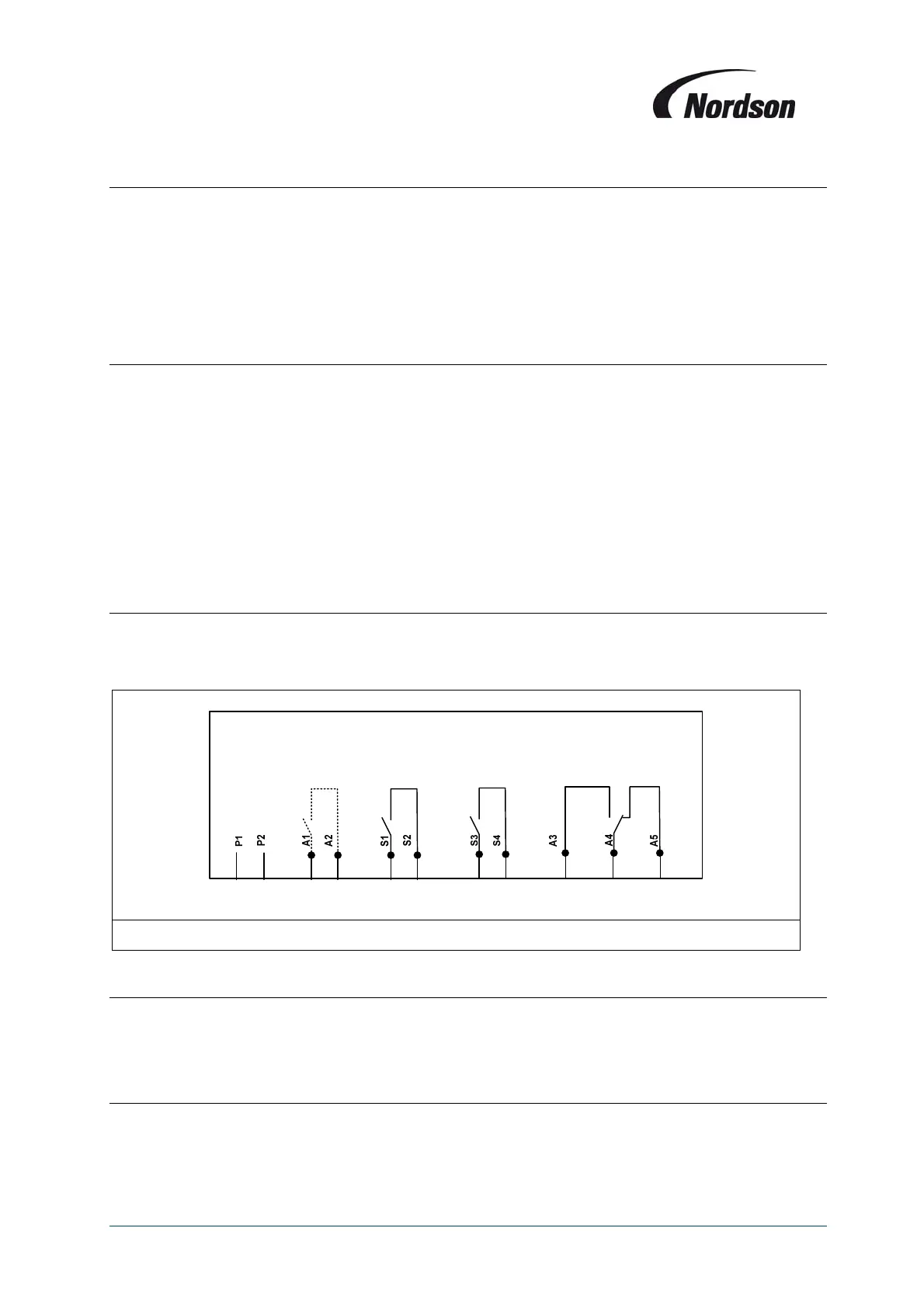
failure occurs (see Figure 3 schematic below).
6 7 8 9 10 11 12 13 18 19 20
Figure 3: Wiring diagram module PCB (detail)
3.9. Remote start/stop push buttons: terminals 21–23
The external ON/OFF push button circuit can be connected to terminals 21-23. The terminals 21 and 22
are connected ex works. To start the fan set: momentarily close contact 23 and 22 (Normally open
contact). To stop the fan set: momentarily open contact 21 and 22 (normally closed contact).
3.10. Input external on: terminal 24, 28
The input terminal 24 can be used to start the filter from an external potential free contact. Closing the
contact = fan start, cleaning operational; opening the contact = fan off. In this case terminals 21 and 22
(remote stop) are bridged.