Installation, Operation and Maintenance Manual
6
1. INTRODUCTION
It is a requirement of the Supply of Machinery (Safety) Regulations 1992 to provide adequate
isolation and emergency stop facilities. Due to the varied nature of site installations this cannot
be provided by Nordson but instead is the responsibility of the customer.
For installation in hazardous areas, all work must be carried out with the electrical supply
isolated or only when the potentially explosive atmosphere is not present. Checks should be
made to ensure the category of equipment is suitable for the zone in which the installation is
made.
All electrical work has to be done by a qualified electrician according to the national and local
electric codes that apply. (EN60204.1, IEC 364).
All electrical power must be shut off during installation of the Control Board.
Do not apply power on any circuits before all connections have been made.
On outside installations, always isolate power before opening the controller in wet weather
conditions.
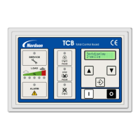
The Control Board provides following functions:
Starting and stopping of the cleaning function at the assigned (adjustable) set points, initiating the
individual pulses in an appropriate sequence, providing the correct time interval between pulses,
energizing the solenoid valve for the proper length of time, and also providing the logic to control
the alternate cleaning modes
Connection of up to 32 valves in parallel mode. (16 valves for the light version - based on 22w /
Valve).
Connection of up to 96 valves in a serial linked, multi module system. (based on 22w / Valve).
Operation of multiple fan systems (e.g. ECB units) under either standard or ‘ATEX‘ mode
cleaning.
An LCD-display showing all settings and alarm messages
Push buttons to start and stop the fan
Overload protection of the fan(s).
A visual display of the pulse cleaning
A bar graph indicating the differential pressure over the filter elements
Possibility to set an adjustable off-line cleaning cycle
A visual display of the off-line cleaning cycle when set
‘Stop-and-go’ or ‘stop-and-end’ setting (explanation: see chapter 7.11)
Programmable input and output functions
Optional remote control installation
Optional alarm installation

 Loading...