Installation, Operation and Maintenance Manual
14
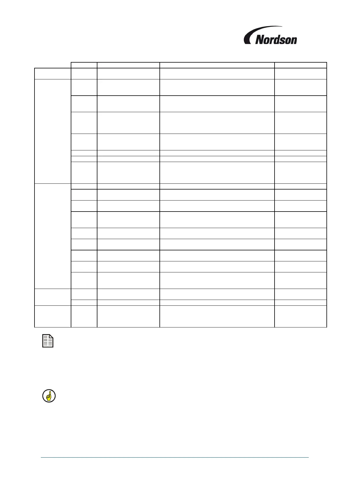
Terminal Item Description Remarks
Bus
Connection
3,4,5 RS 485 Bus connection
Serial link connection between display and I/O
modules
Outputs 8, 9 Thermistor / bursting disc
Relay output signal for Thermistor circuit or bursting
disc Reed-contact.
Max. contact load of
relays: 5 A - 230 VAC
/ 2 A - 24 VDC
10, 11 Programmable output O1
The contact closes during cleaning as default
setting.
(Used for fan 4 in multi-fan ECB configurations)
Max. contact load of
relays: 5 A - 230 VAC
/ 2 A - 24 VDC
12, 13
Optional programmable
output O2
The contact closes during fan operation and off-line
cleaning as default setting.
(Used for lighting circuit in multi-fan ECB
configurations)
Max. contact load of
relays: 5 A - 230 VAC
/ 2 A - 24 VDC
18, 19,
20
General alarm
19 Common, 18 Normally Open, 20 Normally
Closed.
Max. contact load of
relays: 5 A - 230 VAC
/ 2 A - 24 VDC
29, 31 ‘Fan on’ lamp Output for external control lamp “fan set operational” 24VDC, Max load 2W
30, 31 Alarm lamp Output for external control lamp “Alarm” 24VDC, Max load 2W
Optional
32, 33,
34
4-20 mA output signal
Analogue output for differential pressure (4 mA = 0
daPa, 20 mA = 500 daPa).
4 – 20 mA
Recommended
external resistance
150-250 Ω
Inputs
1, 2 Supply voltage 24 V AC Supply voltage for PCB
6, 7 Thermistor / bursting disc
Optional input for Thermistor circuit or Bursting disc
reed contact.
Use a potential free
NC contact
22, 23 Input remote switch ‘ON’
Input to connect a remote switch (in parallel): ON
(terminal 22 holds + 24 VDC)
Use a potential free
NO contact
21, 22 Input remote switch ‘OFF’
Input to connect a remote switch (in parallel): OFF
(terminal 22 holds + 24 VDC)
Use a potential free
NC contact (Supplied
bridged ex-works)
24, 28 Input external ‘ON’
Input to connect an external contact for fan
operation (terminal 28 holds +24 VDC)
Use a potential-free
NO contact
25, 28 Fan alarm input terminal
Overload relay for fan motor (terminal 28 holds + 24
VDC).
Use a potential free
NC contact
26, 28
Programmable alarm input
I1
When contact opens an alarm message is displayed
as default setting.
Use a potential free
NC contact
27, 28
Programmable alarm input
I2
When contact opens an alarm message is displayed
as default setting.
Use a potential free
NC contact
Optional
32, 33,
34
4-20 mA input signal
Analogue 4-20 mA input signal. 32 Ground, 33 in- or
output, 34 common. (ATEX zone 1and 2
applications)
4 –20 mA
Valves
V1 to
16
Valve connection - (minus) Output for the (-) connection of the valves See notes below.
+ Valve connection + (plus) Output for the common (+) connection of the valves.
Fan
14, 15,
16, 17
Contactor fan motor(s)
Terminal 14: Common connection
Terminal 15: Mains contactor (ECB Fan 1)
Terminal 16: Star contactor (ECB Fan 2)
Terminal 17: Delta contacto
(ECB Fan 3)
Max. contact load of
relays: 5 A - 230 VAC
/ 2 A - 24 VDC
Terminals 8 to 20 are connected with potential-free contacts relays.
All valve connections made with the I/O module PCBs must be in numerical sequence without
gaps.
I/O module PCBs have only RS485 bus and valve connection terminals.
Relays used for solenoid control have a maximum loadings as follows:
1.9A (45W at 24V DC) for master I/O module – suitable for connection of 2 valves of 22W in
parallel.
1.0A (25W at 24V DC) for slave I/O modules – 1 pre-connected valves of 22W only.
Only one valve per compressed air manifold can be operated at the same time.