Installation, Operation and Maintenance Manual
27
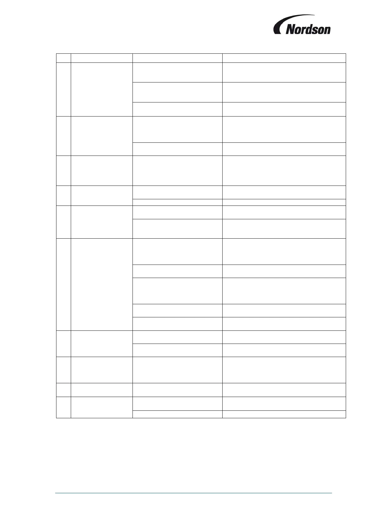
Symptom Possible cause Action
A
Green power-on LED
on module PCB not
illuminated.
Electrical supply fault.
Check supply circuit for proper voltage, fuses,
circuit breakers etc. Replace as required.
Fuse on PCB module blown.
Check wiring connections and replace fuse
with correct type (refer to chapter 11:
Maintenance).
Internal controller failure.
Replace PCB.
B
Fan does not start
and LED ‘Fan on’
(item 7 fig. 1) is not
illuminated.
Main switch on control box open Turn main switch to ON-position.
Electrical supply fault
Check supply circuit for proper voltage, fuses,
circuit breakers etc. Replace as required.
C
The control board is
operational, but the
fan does not start. No
failure is indicated.
Blown fuse
Check the circuit and change fuse F3 (see
wiring diagram supplied with TCB).
D
The automatic circuit
breaker switches off
while the fan starts-up
Delay time between star and
triangle is too short.
Increase change-over time (see chapter 7.7)
Incorrect fan overload setting Check fan overload setting
E
The fan only works in
star operation when
the unit is switched
on; in triangle the fan
stops.
Contactor K2 defective.
Change contactor K2 (see wiring diagram
supplied with TCB)
Incorrect wiring to fan Check wiring from TCB to fan
F
No cleaning pulses
but the LED ‘Pulse
cleaning’ (item 7, fig.
1) is blinking.
Low supply voltage.
Check supply voltage (a low voltage will not
open valves but may operate LED’s normally).
Lack of compressed air for
cleaning.
Increase compressed air pressure for manifold
to 6
7 bar.
Solenoid valves not connected
correctly.
Check connections to solenoid valves in
enclosure or external valve enclosures. Ensure
connection plug is correctly engaged in PCB
socket.
Solenoid valve failure
Check for proper valve action and repair or
replace if necessary.
Diaphragm valve failure
Check for proper valve action and repair or
replace if necessary
G No off-line cleaning.
Off-line cleaning not activated.
Set up controller to off-line cleaning mode
(refer to chapter 7.15).
Off-line cleaning cycles set to ‘0’
Increase number of off-line cleaning cycles
(refer to chapter 7.6)
H
Incorrect/gaps in
valve firing sequence.
Solenoid valves not connected
correctly.
Check connections to solenoid valves in
enclosure or external valve enclosures. Ensure
connection plug is correctly engaged in PCB
socket.
I
Incorrect reading.
Loose connections on
pressure lines.
Check connections for leaks.
J
Incorrect 4-20mA
output.
External circuit resistance too
high.
Reduce external circuit resistance
(recommended range 150-250).
problem
Refer to section I of Fault Location Table.