18
3. Install 240V supply circuit(s) and 24V wir-
ing to closet (see Figure 16 for appropriate
locations).
4. Position optional coil cabinet over floor
cutout and secure with three or more fas-
teners.
5. Position furnace onto coil cabinet and se-
cure with two or more fasteners.
6. Use optional upflow duct connector or field
supplied connector to attach furnace to
overhead supply duct (see Figure 17).
ELECTRICAL SYSTEM
INSTALLATION
!
WARNING:
To avoid the risk of electrical shock,
personal injury or death, disconnect
all electrical power to the unit before
performing any maintenance or
service. The unit may have more than
one electrical power supply.
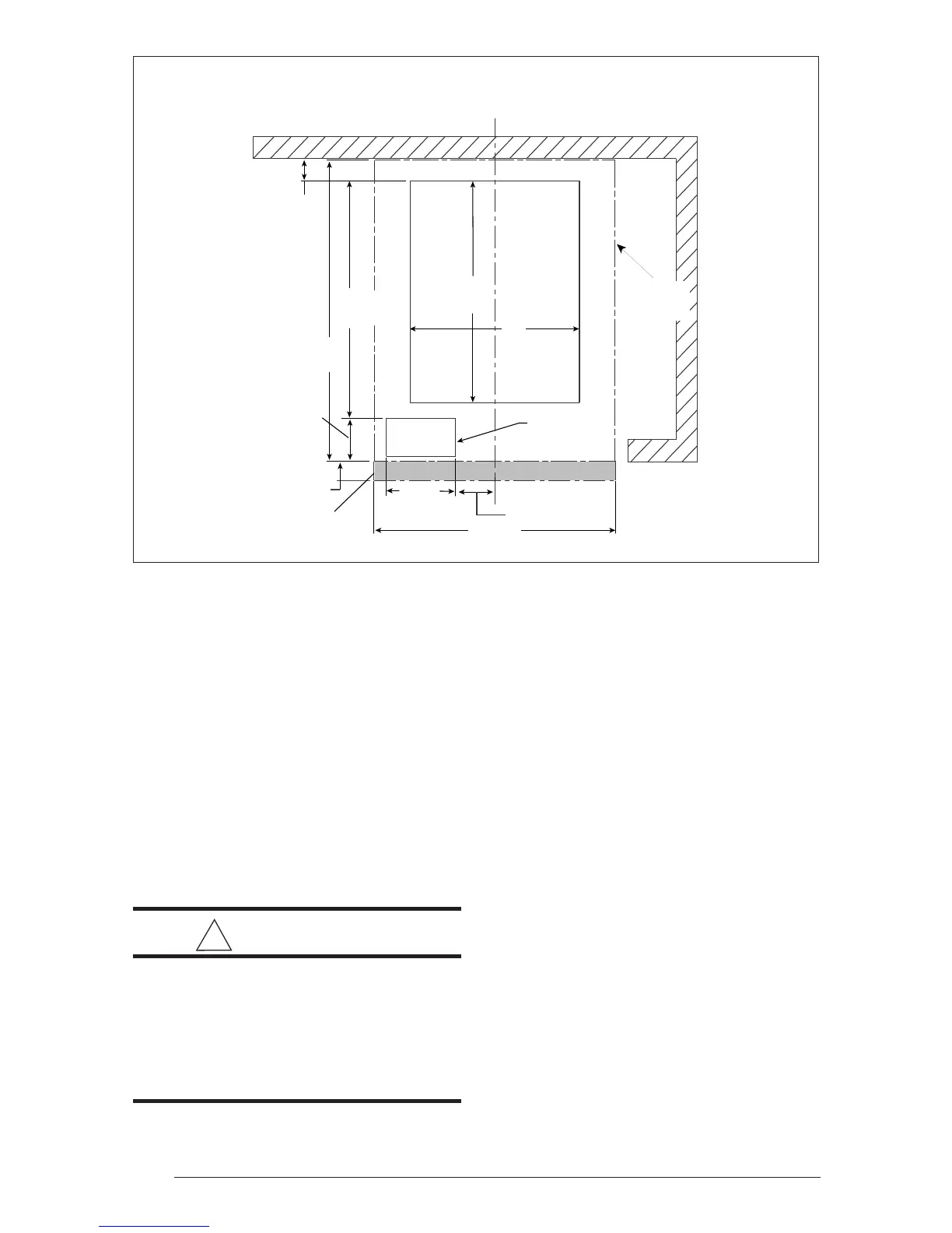
1 3/4" MIN
(45 mm)
23 3/4"
(604 mm)
3/4"
(20 mm)
20"
(508 mm)
17 1/2"
(445 mm)
14"
(356 mm)
5 3/4"
(147 mm)
3 1/8"
(80 mm)
3"
(73 mm)
Furnace
Outer Door
For Optional
A/C Or H/P
REAR WALL OF ENCLOSURE
CENTER LINE
Furnace
Outline
18 5/8"
(474 mm)
Figure 19. Upflow Floor Cutout Locations (nominal dimensions)
Codes, Specifications, and
Requirements
The wiring, installation, and electrical hookup of
this furnace must comply with the National
Electrical Code (or the Canadian Electrical
Code) and all regulations of local authorities
having jurisdiction. See Table 9a & 9b for mini-
mum circuit ampacity, maximum over-current
protection, and recommended wire size. See
the unit wiring diagram for other wiring details.
Supply-circuit requirements are as follows:
• -010 model is factory-wired for single-branch
supply circuit only.
• -012 models are factory-wired for single-
branch supply circuit (single-circuit kit in-
stalled). Dual-branch circuit can be used by
removing factory-installed single-circuit kit
(see Figures 20 and 21).
• -015, -017, -020 and -023 models are
factory-wired for dual-branch supply circuit.
Single-branch circuit can be used by
installing optional single-circuit kit .
 Loading...