21
to terminal 4 on blower relay and is the blue wire
attached to the motor pin terminals 1-3.
a. Remove heating and cooling leads from
motor terminals 1-5.
b. Choose desired speeds and seat terminal
back into motor terminals 1-5.
Same Speed, Heating and A/C: Use loose
white jumper wire supplied with unit and jumper
between terminals 5 & 2 on blower relay. On
E3EX, remove one wire from motor terminals 1-
5.
See Table 6 for blower performance data.
Installing Control Circuit Wiring
NOTE: Installation of a five-wire thermostat
circuit is recommended to provide for future
addition of a heat/cool thermostat.
1. Install the 24V control-circuit cable through
plastic bushing at either side of furnace.
a. For models without a relay box, connect
wires to furnace at blower plug pigtails (see
wiring diagrams). Secure all connections
with wire nuts.
b. For units with a relay box installed, make
wiring connections at relay box low-volt-
age terminal board. (See relay box instal-
lation instructions.)
2. Route control circuit wiring to wall
thermostat and outdoor section, if installed.
(See relay box installation instructions if
applicable.)
3. Set anticipator per Table 7 or per the
marking on the unit.
4. See Figure 31 (non-Platinum) and Figure
32 (Platinum) for E3EB thermostat con-
nections.
SYSTEM CHECKOUT
Checking Installation
1. Refer to appropriate wiring diagram and
recheck all wiring connections. Ensure
that all connections are tight.
2. Check blower motor and relay box
connectors for proper connection.
3. Reinstall control box cover(s).
4. Switch circuit breaker(s) to “ON” position.
5. Set furnace blower selector switch (see
Figure 16) to “AUTO” (EH Units only).
6. Replace outer furnace door.
7. Check all duct connections and tape for air
leakage.
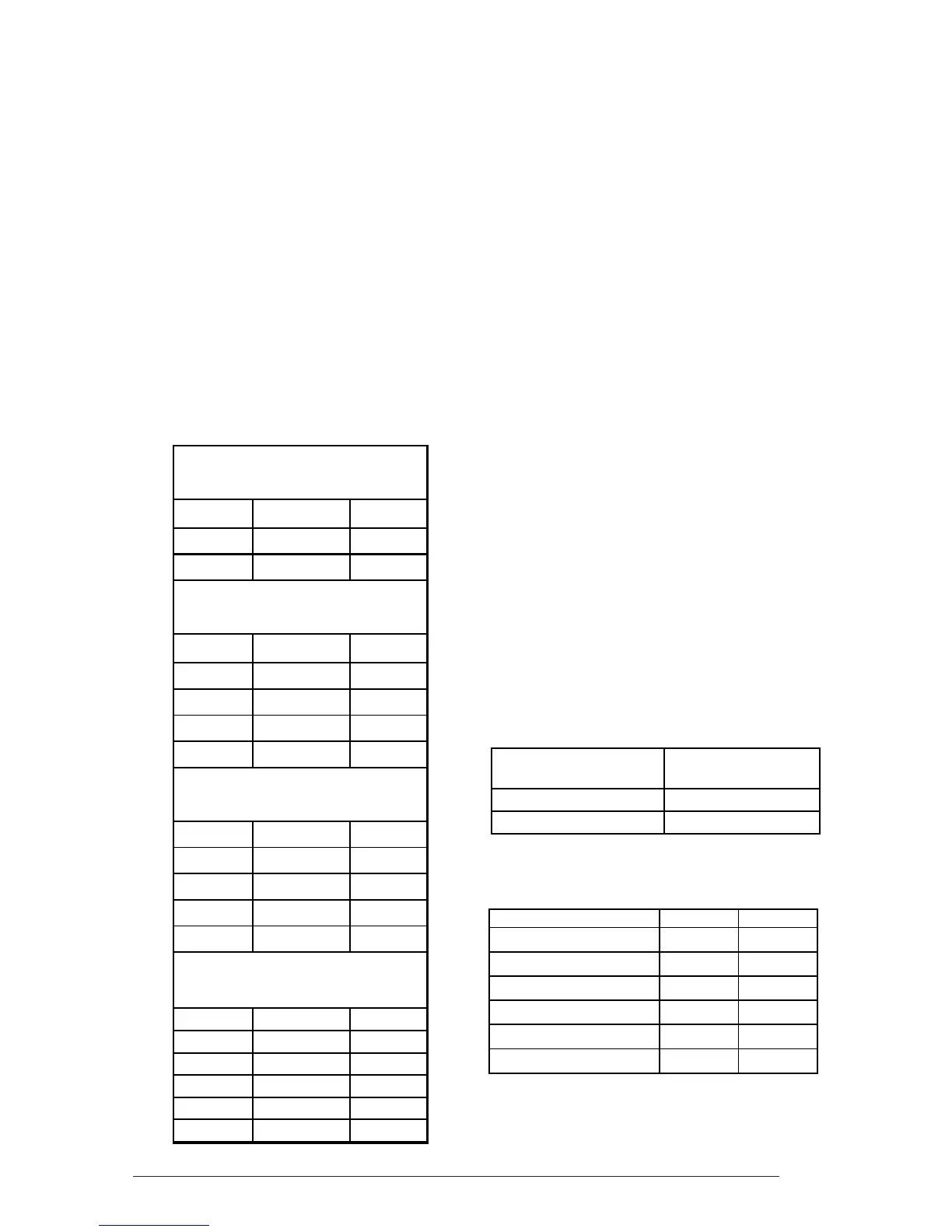
Table 6. Blower Performance
Table 7. Anticipator Settings
Table 8. Clearances
CLOSET ALCOVE
Front ‡ 6" 18"
Back 0" 0"
Sides 0"† 0"†
Top 0" 0"
Top and Sides of Duct 0" 0"
Bottom of Duct 0" 0"
† For upflow application using upflow stand,
Furnace Thermostat
Model Anticipator Setting
010, 012 0.20
015, 017, 020, 023 0.40
Standard E3EH Blower
with Filter, @ 0.3" ESP
Pin No. Speed CFM
#1 Lo w 840
#2 High 1160
4-Ton Blower with Coil and
Coil and Filters, @ 0.3" ESP
Pin No. Speed CFM
#1 Lo w 880
#2 Med.-Low 1170
#3 Med.-High 1310
#4 High 1460
5-Ton Blower, with Coil and
Coil Filters, @ 0.3" ESP
Pin No. Speed CFM
#1 Lo w 990
#2 Med.-Low 1320
#3 Med.-High 1620
#4 High 1790
Multi-Speed, X13, Blower, with
Coil and Filters, @ 0.3" ESP
Pin No. Speed CFM
#1 Lo w 880
#2 Med.-Low 1000
#3 Med 1170
#4 Med.-High 1260
#5 High 1460
 Loading...