23
L
C
ORANGE
BLACK
RED
TRANSFORMER
240V
24V
1
2
3
ELEMENTS
BOTTOM ELEMENTS, 10.0 KW
BLOWER
SWITCH
H
BLACK
BLACK
ORANGE
GREY
BLACK
WHITE
YELLOW
RED
BLACK
BLACK
BLACK
CONTACTOR
LIMITS
RED
4
2
3
1
FUSE
BROWN
VIOLET
GREY
GREY
RED
RED
COM
1
2
3
4
5
6
1
2
3
4
5
6
BLACK
BLACK
RED
RED
YELLOW
RED
BLACK
60A
ON
OFF
Circuit A
Line
Voltage
GRD Ground
Supply
CIRCUIT
BREAKER
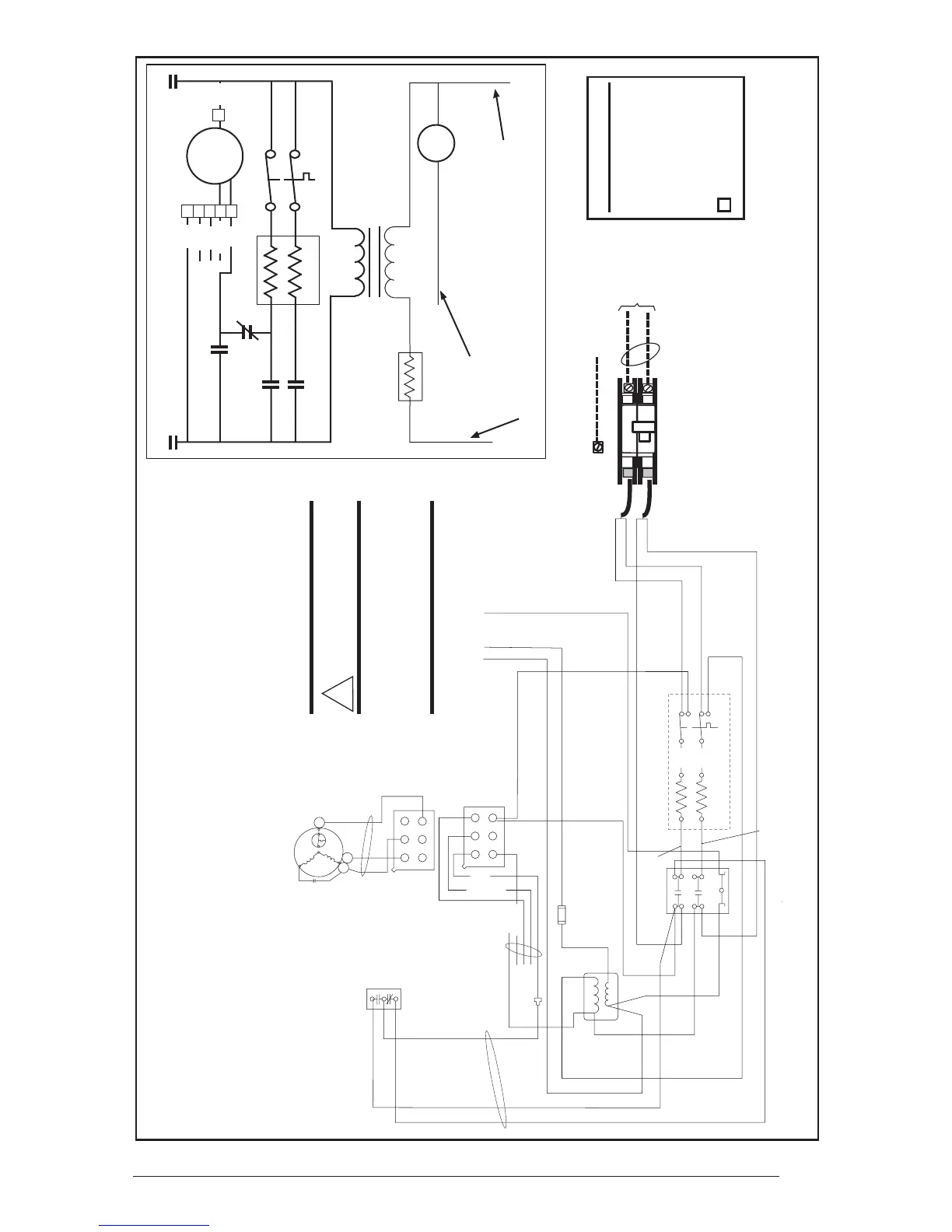
Figure 22. E3EH 010H Wiring Diagrams
NOTES:
1) See unit data label for recommended supply wire
sizes.
2) Thermostat anticipator setting: 0.20 Amps.
3) To change blower speeds on units without a relay box
installed refer to installation instructions.
4) Refer to furnace and/or relay box installation for
thermostat connections.
!
WARNING:
Switch circuit breakers to
the OFF position before
servicing the furnace.
5) If any wire in this unit is to be replaced it must be
replaced with 105°C thermoplastic copper wire of the
same gauge.
6) Not suitable for use on systems exceeding 120V to
ground.
7) This wire is used with some accessories. See acces-
sory Installation Instructions for further details.
Legend:
CB – Circuit Breaker
E – Heater Element
IFS – Fan Switch
Cont – Contactor
LS – Limit Switch
IFM – Fan Motor
– Fan Plug
240V
Transformer
Cont
1
24V
Red Pig-Tail
White Pig-Tail
Cont 1
C
L
IFM
CB-A
CB-A
IFS
LS
Btm - 10.0
6
H
1
2
3
4
5
Red
Blue
Black
E
Cont 1
IFS
Yellow
Grey
Org.
(See Note 7)
Grey Pig-Tail
Fuse
 Loading...