G6RA, G6RK Service Manual 13
Cover
Plate
Nut
Covered Vent
Collar Hole
Looking Down at
Vent Opening
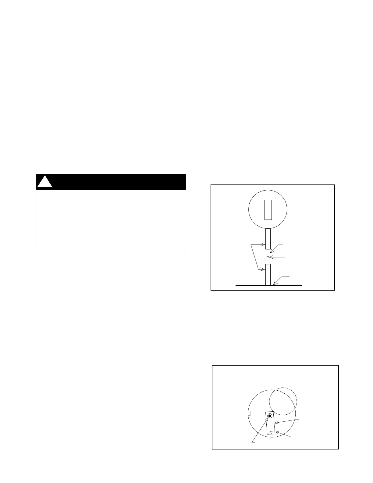
Figure 8. G6RA Bleed Tube Installation
Figure 9. G6RA Vent Collar Detail
The venting system should be designed to have the minimum
number of elbows or turns. All horizontal runs shall be
sloped upwards from the furnace at 1/4 inch per running foot
of vent. Supports for the vent pipe must be installed a
minimum of every five feet along the vent run to ensure no
displacement after installation.
Under no circumstances shall any portion of the vent system
extend into or pass through any return air duct, supply air
duct, or plenum.
If the furnace is operated with blocked or restricted venting,
the blocked vent switch located in the vent plate will open,
turning off the gas supply to the burners. The blocked vent
switch is a manually reset device. DO NOT install a jumper
wire across this switch to defeat its function. DO NOT reset
the switch without identifying and correcting the fault condition
which caused the switch to trip. If this switch must be
replaced, use only the part specified in the Replacement
Parts List.
Category III - Horizontal Venting
NOTE: The reduced NOx models (eighth character N) are not
approved as a Category III (Categorie III) furnace for use with
horizontal venting.
The furnaces are approved for use with 3" single wall AL29-
4C stainless steel vent pipe in horizontal vent applications.
This pipe is available from the following manufacturers:
Z-FLEX Inc. - vent brand name (Z-VENT)
Heat-fab Inc. - vent brand name (Saf-T Vent)
Flex-L International - vent brand name (Star-34 Vent)
This vent pipe must be used for the entire length of the vent
run. The installation must be in accordance with all instructions
supplied by the vent manufacturer for use on Category III
appliances. When venting horizontally this is a Category III
furnace, the vent pressure is positive, and the venting
system must be sealed.
For horizontal venting installations in both the United States
and Canada the transition assembly must be modified, the
bleed tube must be added to the pressure switch tube, and
the vent switch must be by-passed. The bleed tube is found
in an envelope, attached to the furnace literature.
Horizontal Venting For G6RA Models:
NOTE: An optional horizontal vent kit will be required. See
Vent Kit Bleed Tube Chart on Page 40.
1. Remove the rubber tubing from the pressure switch
sensor tube and the collector pan sensor tube. Cut 1/2
inch from one end of the rubber sensor tube, fold in half
and cut along the bend line. Discard the 1/2 inch long
piece and place the other two pieces on both ends of the
bleed tube, do not cover the hole in the bleed tube. Place
the assembly back on the pressure switch sensor tube
and the collector pan sensor tube.
(See Figure 8.)
2. Remove the nut and restrictor plate from the vent collar
assembly and discard the restrictor plate. Remove the
cover plate from the envelope attached to the furnace
literature, and fit the clearance hole over the weld stud.
The cover plate must cover the hole(s) on the vent collar
assembly. Tighten the nut securely while holding the
cover plate in position. (See Figure 9.)
3. Bypass the vent switch by removing both wires from
the vent switch and attaching them to the wire nut.
(See Figure 10.)
Horizontal Venting For G6RK Models:
NOTE: An optional horizontal vent kit will be required. See
Vent Kit Bleed Tube Chart on Page 40.
Collector
Pan
Pressure
Switch
Cut
Sensor
Tubes
Bleed Tube
Bleed Tube
Orifice
WARNING:
Upon completion of the furnace installation,
carefully inspect the entire flue system both
inside and outside the furnace to assure it is
properly sealed. Leaks in the flue system can
result in serious personal injury or death due
to exposure of flue products, including
carbon monoxide.
!
 Loading...